The AnalogOutput component is an IO point (network point class) component that transfers the value to a physical analog output of a device. The component allows to transfer data received from the linked Data Point in order to control the physical analog output of the device, and allows to set the polling mode of the point. The component can pass data from the Data Point class component by linking Reference slots; the AnalogOutput component may be linked from an Analog Data Point.
In order to operate properly, the AnalogOutput component must be located under the Local IO component in the Networks container.
Note: Before using the component, make sure that its individual address is assigned and its Status is OK.
The AnalogOutput component includes an action that allows to set its Out value in case no Data Point class component is linked to it.
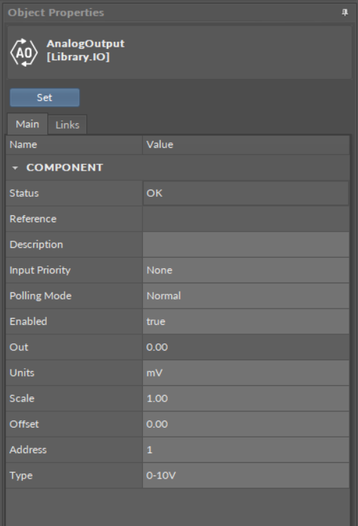
The AnalogOutput component
Slots
The Analog Output component has the following slots:
-
Status: indicates the current status of the component; if the component works properly, its status is OK. The component becomes Disabled, once the Enabled slot is in false. The component's status is Fault, once the Address slot is null, 0, or exceeding an available range;
-
Available information: Disabled, Fault, OK;
-
-
Reference: a special slot allowing to connect network point class components with Data Point class components. It allows to transfer the Out slot value along with the component's status.
Note: Reference links from Data Points to network points also transfer values in the opposite direction, in a link-back-from process: having received a value by the Reference link, the network point transfers it back to the Data Point to whichever input priority from 1 to 16 is set in the network point.
Note: The Reference links work on a change-of-value. If a value in the Data Point's Out slot changes, it is immediately transferred to a network point linked by the Reference link–such change is not dependent on an application cycle.
-
Description: an additional detailed information about a component that may be freely described by the user; the description may contain individual coding, defined in the user's system documentation, meter's or sensor's location, or any other information the user finds applicable.
-
InputPriority: allows to indicate the input number in the Data Point, which the network point class component's output value is sent to, in case the network point detects the change on its Out slot; by default, the priority is none.
-
Available settings: none, 1-16.
-
-
Polling Mode: allows to set the frequency of sending polling requests for the point's value—by default, the polling mode is set to normal;
-
Available settings: fast, normal, slow;
-
-
Enabled: change of the slot's value enables or disables the component—if the component becomes disabled, it stops to transfer values to the physical output; by default, the component is enabled.
-
Available settings: true (enabled), false (disabled).
-
Note: If the Enabled slot is in false (meaning the component is disabled), the Status slot becomes Disabled.
-
Out: displays a value transferred to the output of the address set in the Address slot.
Note: If the component's Status is fault (e.g., an invalid value in the Address slot), the Out value is null.
-
Units: defines a unit of the Out slot value, depending on the selected mode of operation—the unit is automatically set once the mode type is selected in the Type slot, however, it can be manually adjusted by the user;
-
Available units: according to BACnet units;
-
-
Scale: sets a fixed scaling factor for output linearization; the value transferred to a physical output is calculated according to the inversed linear function y=(x-b)/a, and recalculated according to the linear function y=ax+b to the Out slot; the Scale slot sets the a value of the formula;
-
Offset: sets a fixed offset value to the output value; the value transferred to a physical output is calculated according to the inversed linear function y=(x-b)/a, and recalculated according to the linear function y=ax+b to the Out slot; the Offset slot sets the b value of the formula;
Example
The output linearization allows to adjust an output value to the requirements of a controlled device/equipment. For example:
-
if an analog output controls an actuator, which operates within a 2-10 V range, the AnalogOutput component can be scaled to produce output fitting the required range:
-
the Type slot set to 0-10 V;
-
the Scale slot value set to 1.25 (10000 mV/8000 mV);
-
the Offset slot value scaled to -2500 (redefining the output's range to 2-10 V: 2000 mV/0.8 range).
-
Note: Though the Type slot is set to 0-10 V, the actual value is controlled in mV. Accordingly, the offset must be set in mV.
-
to scale the output to control a device, which operates within a 0-5 V range, the AnalogOutput parameters have to be set as follows:
-
the Type slot set to 0-10 V;
-
the Scale slot value set to 2;
-
the Offset slot value scaled to 0.
-
-
to translate 0-100% to 0-10000 mV, the AnalogOutput component can be scaled to produce output fitting the required range:
-
the Scale slot value set to 0.01 (100%/10000 mV);
-
the Offset slot value scaled to 0.
-
Note: Incorrect scaling of the results in the calculated values (exceeding the available range for the device, e.g., 0-10 V), results in indicating a different value on the input from Reference link and on the Out slot. If the scaling is correct, the values are identical.
-
Address: allows setting an address of a physical output of the device; once the component has been added, the slot's default value is null—for the component to operate properly, the unique address value must be set in this slot.
-
Available settings: 1-n, where "n" stands for the number of actual outputs in the device.
-
-
Type: defines the mode of operation—the component may operate as a voltage or digital output, or in pulse width modulation mode; once the component has been added, the component's mode is set to Voltage;
-
Available modes: Voltage, Digital, PWM001Hz, PWM01Hz, PWM1Hz, PWM10Hz, PWM100Hz.
-
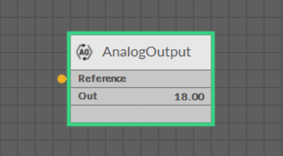
The AnalogOutput component linked
Action
-
Set: sets a value to the Out slot—in case no Data Point is linked to the output network point, it is possible to set its Out value with this action.