A proper configuration of an application cycle, according to expected results, is essential in the iSMA-B-AAC20 controller due to a possibility of getting unexpected outcomes. An inaccurately set application cycle (the 'Scan Period' slot in the 'app' component) can result in losing values read in cyclic communication (e.g., Modbus), losing time-related values calculated in components, or missing pulse changes of values on digital inputs (in LocalIO), which translates to mismanagement of the control process compared to what has been anticipated.
While adjusting the application cycle, it is advised to set the 'Scan Period' value (time set to execute one application cycle) to be higher than the 'Scan Time' value (exact time used to execute last application cycle).
Losing values read in cyclic communication (e.g., Modbus)
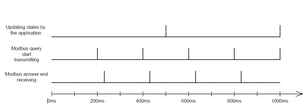
Setting the 'Fast Rate' slot (frequency of a fast polling mode) in the 'ModbusTcpNetwork' component to 200 ms with the application cycle set to 500 ms (in the 'ScanPeriod' slot) does not make sense. In such case, Modbus (on the firmware level) sends 5 requests per 1 minute and with no interruptions on the bus receives 4 answers. However, the application (on the Sedona Virtual Machine level) takes only the second and fourth Modbus requests to the logic (not the fifth, as a minimum time of several ms is required to read an answer from a requested device). The situation is clearly illustrated below:

Figure 1. Timeline illustrating moments of sending requests and receiving answers in the Modbus protocol (Fast Rate set to 200 ms) and moments when components in the application update their values
Here, it would be advised to reduce the application cycle in the 'Scan Period' slot (to less than 200 ms) if that was the communication requirement, or to extend the 'Fast Rate' if the controller was so overloaded that the 'Scan Time' would not let reaching so high polling frequency. Otherwise, the application logic will not incorporate all frames and the network bandwidth will still be busy with unused frames.
Losing time-related values calculated in components
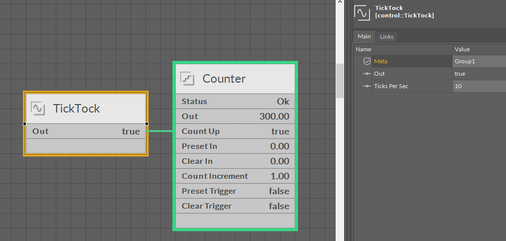
Time-related components can operate inaccurately if the application cycle is improperly set. For illustration purposes, an example logic has been created. The 'Out' slot of the 'TickTock' component from the 'control' kit (the 'Ticks Per Sec' slot set to 10) is linked to the 'Count Up' slot of the 'Counter' component from the 'iSMA_control' kit (the 'Count Increment' slot set to 1), and the main application cycle in the 'Scan Period' slot is set to 100 ms:

Figure 2. Configuration of the example logic based on the 'TickTock' and 'Counter' components
Setting the 'Ticks Per Sec' slot to 10 means that the component changes its state 20 times per second ('false->true and true→false' repeated 10 times), which translates to 1 change of state every 50 ms. In this configuration (with the 'Scan Period' slot is set to 100 ms), in can be observed that the 'Out' slot of the 'TickTock' component is constant ('true') and the Counter has not increased. It is consistent with the application cycle, as at the beginning of the cycle the application reads current states of all input slots for application ('LocalIO', Timer, etc.) and calculates further components ('Add, 'Mul', etc.) based on the input values. The figure below depicts the process:

Figure 3. Timeline illustrating changes of state of internal variables in the 'TickTock' components ('Ticks Per Sec' set to 10) and the 'Out' slot considering the main application cycle (100 ms)
Changing the 'Ticks Per Sec' slot to 5 results in changing the state every 100 ms (same as the application cycle), and in this case, the Counter registers 5 pulses per second, as illustrated below:

Figure 4. Timeline illustrating changes of state of internal variables in the 'TickTock' components ('Ticks Per Sec' set to 5) and the 'Out' slot considering the main application cycle (100 ms)
Losing pulse changes of state on digital inputs (and universal inputs in digital mode)
In the iSMA-B-AAC20 controller, reading input values ('LocalIO') and writing digital/analog/universal output values is updated in components from the 'iSMA_localIO' kit according to the application cycle ('Scan Period'). It means that with a default (200 ms) or longer (e.g., 500 ms, 1000 ms) application cycle input state signals (particularly for digital inputs) have to be sustained long enough for the application to read them (min. 1 application cycle).
It also translates to the functioning of the controller's logic - the application first updates a digital signal, than calculates it in the logic, and, lastly, updates the output state.
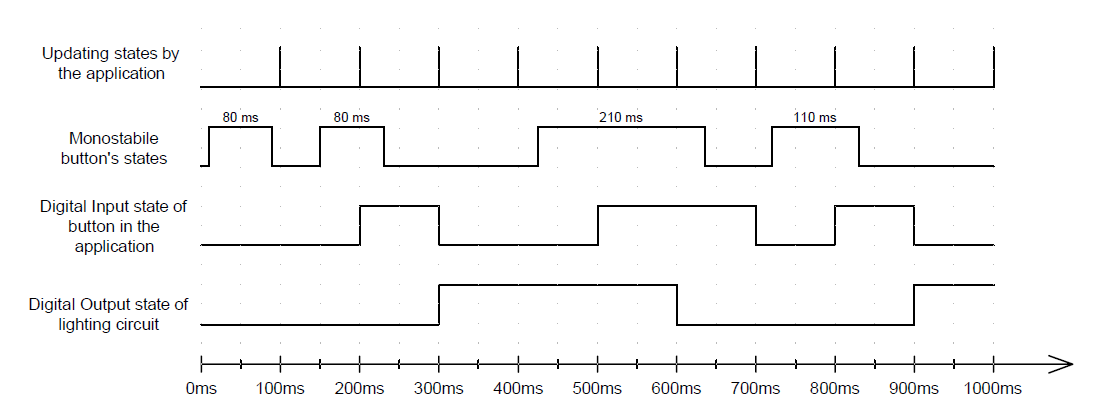
One of the most vulnerable applications is the one controlling lights with a monostable switch. Pulses generated in practice by the monostable switch can be mechanically held for a time from 80 ms up to much longer depending on how long someone presses the switch. Obviously, the change of state is expected after the press. However, with the application cycle ('Scan Period') slower than the shortest pulse, the pulse can simply miss the application reading inputs' states. It means that the controller can miss some of requests to change the lighting (for this process, the application cycle set to 100 ms is too slow). The figure below shows several switches with different times of holding compared with the application cycle of 100 ms:

Figure 5. Timeline illustrating moments when the application updates states of inputs (the application cycle of 100 ms), mechanical changes of the monostable switch state, values of the digital input and digital output linked to the logic, which changes its value on the rising edge of the digital input
For this reason, it is not advised to involve in the logic monostable switches and pulse outputs (e.g., counters or flowmeters) in large applications in the iSMA-B-AAC20 controller.
The way to optimize the application for such functionality is to reduce the application cycle to minimum, and all processes that are not time-related should be based on the 'RateFolder' components (described in this article). It is also advised to set the 'App Cycles To Skip' slots in 'Rate Folder' components to a high prime number (mathematical definition). Then, each 'Rate Folder' is executed in different controller's cycle and only sporadically overlaps with the main application cycle (multiples of prime numbers overlap very rarely, and the bigger the prime number, the less chance for cycles to coincide).
