The VAV14-IP device is equipped with an RS485 port with two connectors: RJ45 and screw connector, which translates to the universal functionality of the RS485 port.
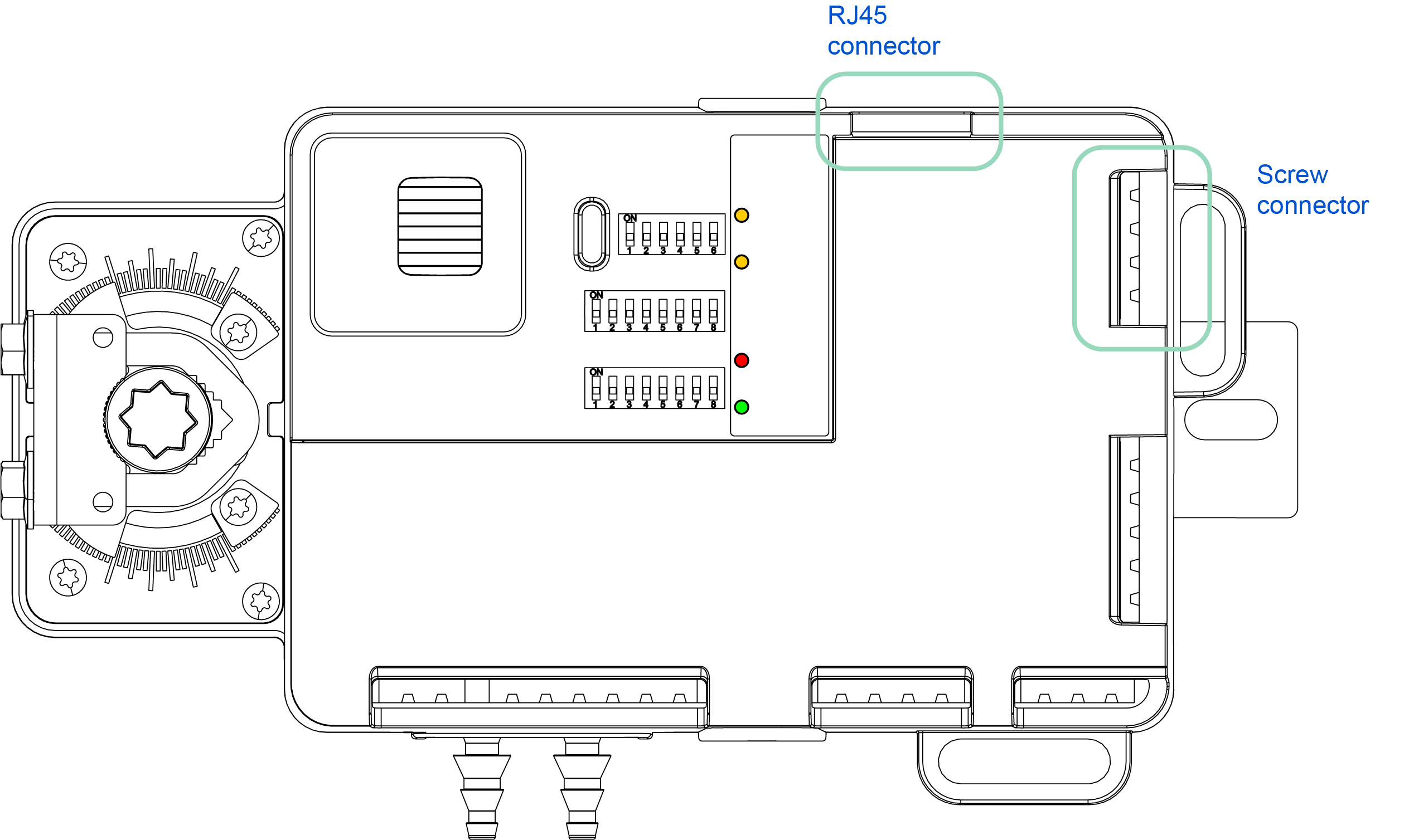
RJ45 Connector
The RJ45 connector allows to connect a dedicated room panel.
The RJ45 socket also provides power supply dedicated for external room panel.
RS485 Screw Connector
The RS485 port is also equipped with a screw connector, which allows connecting with other devices in the network.
The screw connector allows to connect separable cables of diameter as thin as 2.5 mm2 (18 – 12 AWG).
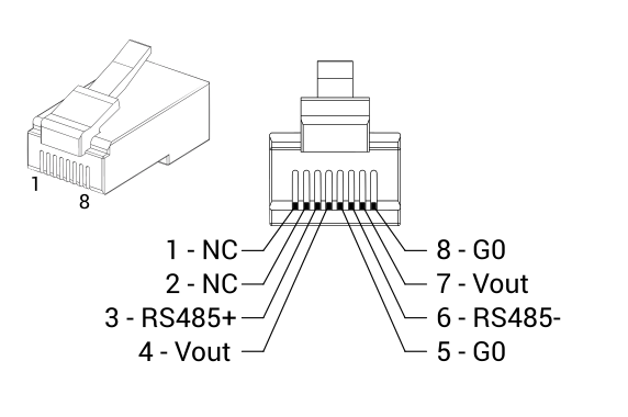
RS485 Pins
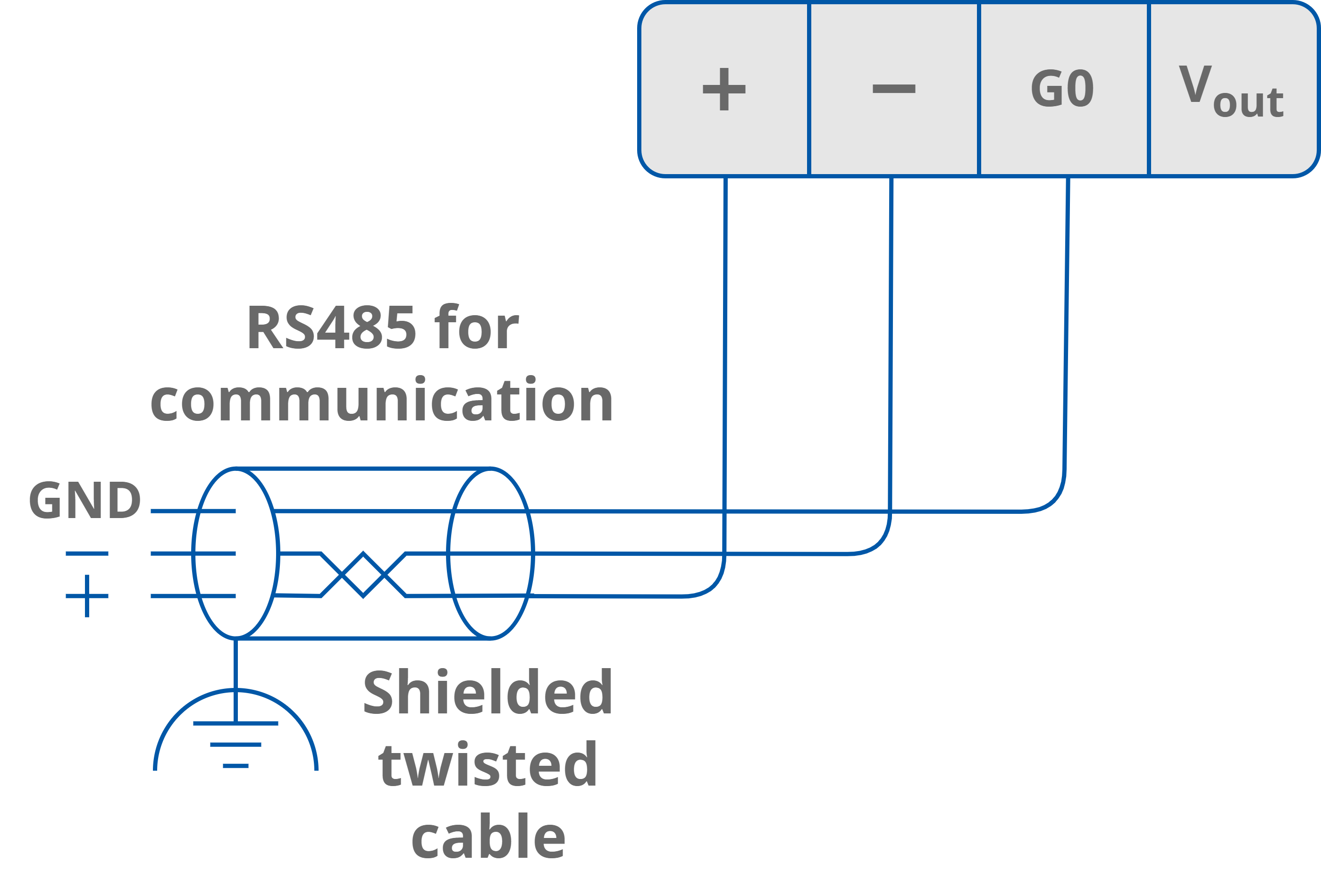
RS485 Grounding and Shielding
In most cases controllers are installed in enclosures along with other devices, which generate electromagnetic radiation (for example, relays, contactors, transformers, motor invertors, etc.). Such electromagnetic radiation can induce electrical noise into both power and signal lines, as well as direct radiation into the controller, causing negative effects on the system. For this reason, an appropriate grounding, shielding, and other protective steps should be taken at the installation stage to prevent negative electromagnetic radiation effects, for example:
-
control cabinet grounding;
-
cable shield grounding;
-
using protective elements for electromagnetic switching devices;
-
proper wiring;
-
consideration of cable types and their cross sections;
-
and other.
RS485 Network Termination
Transmission line effects often present problems for data communication networks. These problems include reflections and signal attenuation.
To eliminate the presence of reflections of signal from the end of the cable, the cable must be terminated at both ends with a resistor across the line adequate to its characteristic impedance. Both ends must be terminated since the propagation is bidirectional. In case of an RS485 twisted pair cable this termination is typically 120 Ω.
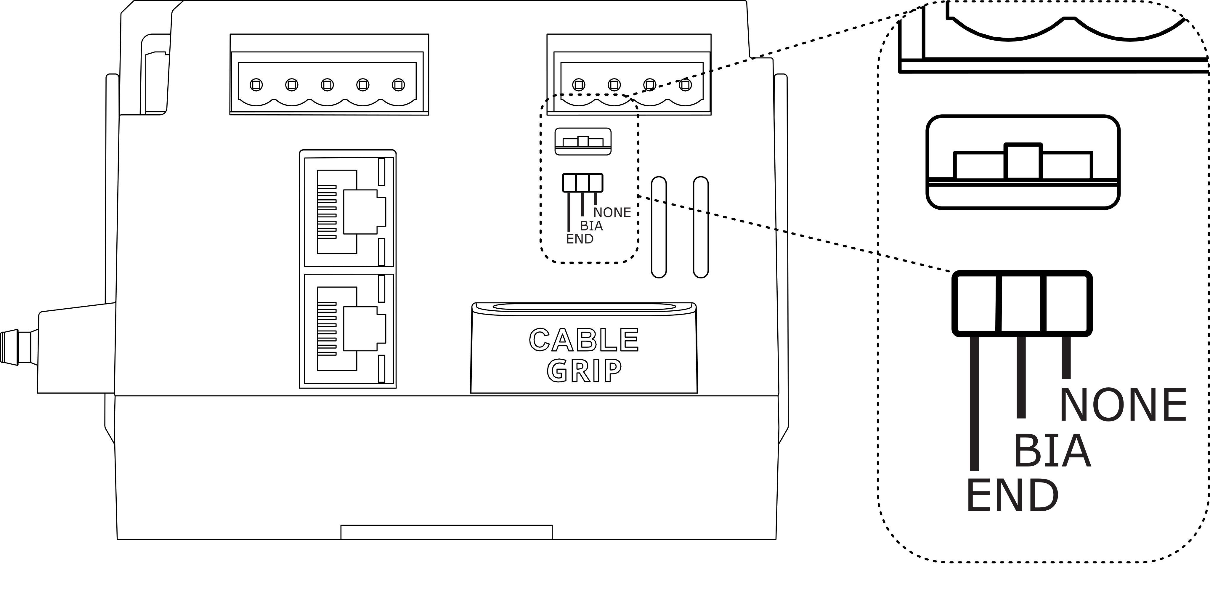
In the VAV14-IP there is a built-in, 3-position switch on the right side of the device, which is dedicated to connecting termination resistor and/or biasing resistors.
|
Switch Position |
Biasing |
Termination 120 Ω |
|---|---|---|
|
NONE |
Off |
Off |
|
BIA |
On |
Off |
|
END |
On |
On |
Instead of using additional resistors, the termination and biasing can easily be done by a simple switch activation.
If the switch is in the END position, it connects the termination resistor 120 Ω and biasing resistors 680 Ω (pull-down to ground G0 and pull-up to +5 V DC) to the RS485 bus.
If the switch is in the BIA position, it connects the biasing resistors 680 Ω (pull-down to ground G0 and pull-up to +5 V DC) to the RS485 bus. The biasing is added to the RS485 bus in order to reduce communication failures.
By default, the switch is set to the NONE position, both biasing and termination are off.
Warning!
Only one single device on the network can have biasing resistors connected. Connecting biasing resistors on two or more devices on a single RS485 bus will take the opposite effect–increase the number of communication problems.