The UniversalInput component is an IO point (network point class) component that retrieves data from the physical universal input of a device. The component allows to configure the universal input according to its purpose—the universal input may serve as a voltage, current, digital, resistance, or temperature input—in order to communicate properly with the linked Data Point. The component allows to change the type of sensor, its resolution, and to apply an input signal filtering.
The component can pass data to the Data Point class component by linking Reference slots; the UniversalInput component may be linked to an Analog Data Point. In order to operate properly, the UniversalInput component must be located under the LocalIO component in the Networks container and have its unique number assigned in the Address slot.
Note: Before using the component, make sure that its individual address is assigned and its Status is OK.
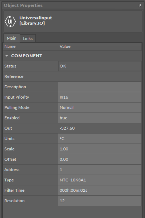
The UniversalInput component
Slots
The UniversalInput component has the following slots:
-
Status: indicates the current status of the component; if the component works properly, its status is OK. The component becomes Disabled, once the Enabled slot is in false. The component's status is Fault, once the Address slot is null, 0, or exceeding an available range;
-
Available information: Disabled, Fault, OK;
-
-
Reference: a special slot allowing to connect network point class components with Data Point class components. It allows to transfer the Out slot value along with the component's status.
By default, once the Reference link is created from the network point to the Data Point it sets the input priority to 16, which later can be changed manually.
-
Description: an additional detailed information about a service that may be freely described by the user; the description may contain individual coding, defined in the user's system documentation, or any other information the user finds applicable.
-
InputPriority: allows to select the input number in the Data Point, which the value from the network point class component's output is sent to; by default, the priority is None and sets to 16 after linking with a Data Point (can be changed manually).
-
Available settings: none, 1-16.
-
Note: The Reference link from the network point to the Data Point cannot be changed to a 17th, default, priority.
-
Polling Mode: allows to set the frequency of sending polling requests for the point's value—by default, the polling mode is set to normal;
-
Available settings: fast, normal, slow;
-
-
Enabled: change of the slot's value enables or disables the component—if the component becomes disabled, it stops to read values from the physical input; by default, the component is enabled.
-
Available settings: true (enabled), false (disabled).
-
Note: If the Enabled slot is in false (meaning the component is disabled), the Status slot becomes Disabled.
-
Out: a real value read from the physical input of the address set in the Address slot.
Note: If the component's Status is fault (e.g., an invalid value in the Address slot), the Out value is null.
Note: The Out slot value depends on the input type defined in the Type slot.
-
Units: defines a unit of the Out slot value, depending on the sensor type set in the Type slot—the unit is automatically set once the sensor type is selected in the Type slot; however, it can be manually adjusted by the user;
-
Available units: according to BACnet units;
-
-
Scale:
sets a fixed scaling factor for output linearization; the Out value is calculated according to the linear function formula (y=ax+b), and the Scale slot set the a value of the formula;
-
Offset: sets a fixed offset value to the output value; the Out value is calculated according to the linear function formula (y=ax+b), and the Offset slot set the b value of the formula;
-
Address: allows setting an address of a physical input of the device; once the component has been added, the slot's default value is null—for the component to operate properly, the unique address value must be set in this slot.
-
Available settings: 1-n, where "n" stands for the number of actual inputs in the device.
-
-
Type: defines a sensor type for proper reading of values.
-
Available settings: Voltage, Current, Digital, Resistance, Temperature (supported temperature sensors:
-
Celsius degrees: NTC 10K3A1, NTC 10K4A1, NTC 10K Carel, NTC 20K6A1, NTC 2,2K3A1, NTC 3K3A1, NTC 30K6A1, NTC SIE1, NTC TAC1, NTC SAT1, PT1000, NI1000, NI1000 21C, NI1000 LG,
Fahrenheit degrees: NTC 10K Type2, NTC 10K Type3, NTC 20K NTC, NTC 3K, PT1000, NI1000 32F, NI1000 70F).
Note: Choosing one input type disables the rest—the universal input works only as a type defined in the InputType slot, and it will not adjust automatically if the incoming value changes its type. By default, the NTC 10K3A1 temperature sensor is set as an input type; if any other input type is relevant for the particular universal input, it needs to be adjusted manually.
-
Filter Time: sets the filtering period in order to avoid the read values peaks.
-
Available settings: 0-60 s (by default, the filtering time is set to 2 s).
-
-
Resolution: defines a precision of data conversion from analog data to bits for further data processing in the controller's software.
-
Available settings: 12 or 16-bit (12-bit resolution provides fast data processing, whereas 16-bit resolution provides more precise data; however, it may hamper the speed of data processing).
-
Note: As the default value of the Resolution slot is 12-bit, it needs to be emphasized that PT1000 and NI1000 temperature sensors work correctly only with the 16-bit resolution; therefore, if these types of sensors are set in the Type slot, the Resolution slot is automatically adjusted to a 16-bit value.
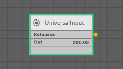
The UniversalInput component linked