A link is a way of exchanging data between components. It connects components between which the data are exchanged. The link identifies which parameter is taken into account on both sides of the connection. This allows to show the data flow direction, i.e., where a specific parameter is read and where it is saved.
The Wire Sheet view shows the link as a line connecting two components. The topic is further discussed in Adding and Removing Links). The Workspace Tree window and the Property Sheet view do not show information about existing links at all.
Views designed to check links for a specific component are the Wire Sheet view and the Links view (available in the links tab in the Object Properties window), which will be discussed in Links Tab).
To create a link between components, in most cases a universal Link Mark method can be used, available in the context menu opened on a source component. Next, the context menu needs to be opened on a target component and the option Link From has to be chosen. That way the user will define a source and target components to create a connection (link). Now, the slots, which will send and receive data, need to be defined in both components. For this purpose, after using the Link From function, a dialog window opens allowing the user to choose a slot both on source component side as well as on target component (see the figure below).
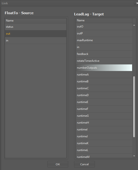
Dialog window for linking components
The iSMA Tool allows to link only the fitting slots of the same data type making creation of a faulty link impossible–once the source slot is selected, only the fitting target slots are highlighted.