WARNING! Changing the parameters concerning the transmission configuration (except for registers which value is read from the switch) only takes effect after restarting the unit.
VERSION_TYPE (30001)
In this register the type and firmware version of the module are encoded.
Low byte contains information about the type of module. High byte contains the module firmware version multiplied by 10.
|
Value |
Type |
|---|---|
|
11410 (0x7216) |
2D1B-(WD) |
|
11510 (0x7316) |
2D-(WD) |
Version Type register
Example:
In the 30001register, there is a following number: 2919410 = 0x720A16. It means that it is a iSMA-B-2D1B (0x72) with firmware in version 1.0 (0x0A16 = 1010).
VERSION_TYPE: Device Actions (40001)
Setting the 40001 register according to the table below enables 1 of 4 available actions: reset module, reload settings, set to default, and enter bootloader.
|
Value |
Action |
|---|---|
|
511 |
Reset |
|
767 |
Reload settings |
|
1023 |
Set to default |
|
1279 |
Enter Bootloader |
Device actions
ADDR_DIPSWITCH (30002)
The register contains the number which represents the controller address set by the MAC DIP switch.
DIPSWITCH_CFG_REGISTER (30003)
The register contains an integer value representing actual configuration of the CFG DIP switch.
RECEIVED_FRAMES_COUNTER (30004)
The 32-bit register with the number of valid Modbus received messages by the device from last powered up. The value is reset after power cycle or after changing transmission parameters (speed, stop bits, parity, etc.).
ERROR_FRAMES_COUNTER (30006)
The 32-bit register with the number of Modbus errors sent by the device recently powered up. The value is reset after power cycle or after changing transmission parameters (speed, stop bits, parity, etc.).
TRANSMITTED_FRAME_COUNTER (30008)
The 32-bit register with the number of Modbus messages sent by the device recently powered up. The value is reset after power cycle or after changing transmission parameters (speed, stop bits, parity, etc.).
UP_TIME (30012)
The 16-bit register contains information about device working time, in seconds, from the last power up or reset.
BAUD_RATE (40017)
If sections 1, 2, and 3 of S3 switch are in off position, the baud rate is determined in accordance with this register. Baud rate is determined by the following formula:
Baud rate = register value • 10
The default value of the register is 7680 (76800 bps).
STOP_BITS (30018)
The number of stop bits is constant and equals 1.
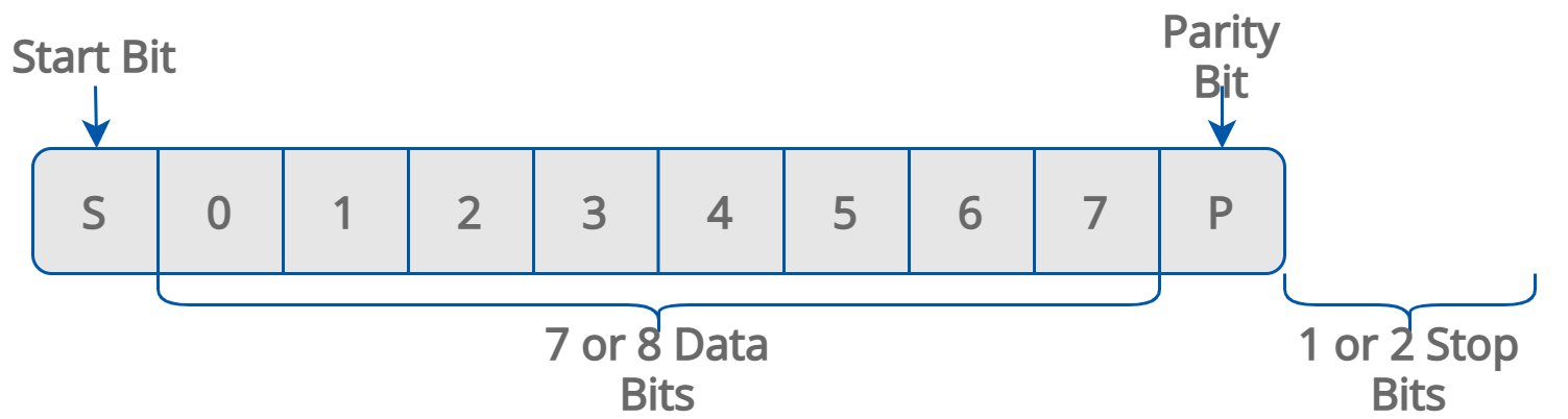
Modbus frame
DATA_BITS (30019)
The number of the data bits is constant and equals 8.
PARITY_BITS (30020)
The type of parity bit is constant and it is 0. It means that there is no parity bit in the Modbus message frame.
REPLY_DELAY (40021)
The value of this 16-bits register determines the number of milliseconds to wait before the unit answers the question. This time is used to extend the interval between question and answer. The default value of 0 means no delay (the answer is sent when the 3.5 character is required by the Modbus RTU protocol).
DIPSWITCH_CFG_REGISTER (30156)
The register contains an integer value representing actual configuration of the CFG DIP switch.
DI1_DI2_SWITCH_TYPE (30156) Bit 0
The bit state shows the actual physical state of the segment 1 in the CFG DIP switch.
If the bit is active (bit 0=1), the digital inputs 1 and 2 are dedicated to work with bistable switches.
If the bit is inactive (bit 0=0), the digital inputs 1 and 2 are dedicated to work with monostable switches.
DI1_CONTROL_MODE (30156) Bit 1
The bit state shows the actual physical state of the segment 2 in the CFG DIP switch.
If the bit is active (bit 1=1), the digital input 1 controls DALI1 and DALI2 interfaces (light output 1 and light output 2).
If the bit is inactive (bit 1=0), the digital input 1 controls the DALI1 Interface (light output 1).
SI1_CONTROL_MODE (30156) Bit 2
The bit state shows the actual physical state of the segment 3 in the DIP switch CFG.
If the bit is active (bit 2=1), the special input 1 controls DALI1 and DALI2 interfaces (light output 1 and light output 2).
If the bit is inactive (bit 2=0), the special input 1 controls the DALI1 interface (light output 1).
DI2_CONTROL_MODE (30156) Bit 3
The bit state shows the actual physical state of the segment 4 in the CFG DIP switch.
If the bit is active (bit 3=1), the digital input 2 controls DALI1 and DALI2 interfaces (light output 1 and light output 2).
If the bit is inactive (bit 3=0), the digital input 2 controls the DALI2 interface (light output 2).
SI2_CONTROL_MODE (30156) Bit 4
The bit state shows the actual physical state of the segment 5 in the CFG DIP switch.
If the bit is active (bit 4=1), the special input 2 controls DALI1 and DALI2 interfaces (light output 1 and light output 2)
If the bit is inactive (bit 4=0), the special input 2 controls the DALI2 interface (light output 2).
LIGHT_CONTROL_MODE (30156) Bit 5
The bit state shows the actual physical state of the segment 6 in the CFG DIP switch.
If the bit is active (bit 5=1), the ON/OFF light control mode is active.
If the bit is inactive (bit 5=0), the DALI interface control mode is active (single or multi).
DI3_DI4_SWITCH_TYPE (30156) Bit 6
The bit state shows the actual physical state of the segment 7 in the CFG DIP switch.
If the bit is active (bit 6=1), digital inputs 3 and 4 are dedicated to work with bistable switches.
If the bit is inactive (bit 6=0), digital inputs 3 and 4 are dedicated to work with monostable switches.
BLIND_CONTROL_MODE (30156) Bit 7
The bit state shows the actual physical state of the segment 8 in the CFG DIP switch.
If the bit is active (bit 7=1), the blind output is dedicated to control the blinds (without slats control).
If the bit is inactive (bit 7=0), the blind output is dedicated to control the shutters (slats control).