The Application component is a component designed to create a user application. By default, the Applications container includes one Application component. However, the user may add as many Application components in the container as needed. The user application is constructed with Data Points and other components (though, it is not a requirement to include Data Points in each user application). The number of Data Points used across user applications must not exceed the license limit. Each Application component allows to create one independent and cycle driven user application.
The Application component can added to the Applications container in two ways:
-
in the Applications Manager;
-
dragging and dropping it directly from the Core library in the Device Libraries window.
The user application is created in the Wire Sheet view.
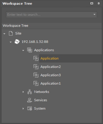
The Application components in the Applications container
The Application component operates in one special view—the Application Manager—and the standard iC Tool views—the Wire Sheet and Property Sheet. The Application Manager allows to add, remove, copy, or duplicate Data Points and the Folder or Equipment components and to add or remove Data Points' extensions. The Property Sheet view presents a list of configurable slots and read-only slots, which provide essential information about the work of the component. Application building is carried out in the Wire Sheet view.
The Wire Sheet view presents Data Points included in the application and other components that introduce dependencies between Data Points. Data Points may be defined for input or output network points and be connected to other components creating the application logics.
Linking within the applications in the iC Tool may be performed twofold: using a standard linking method or using a special Reference link designed specifically to connect Data Point class components with network point class components:
-
The Reference link is a special compound link designed to connect Data Points with network points. The Reference link is created between special Reference slots and transfers values along with the component's status. Alternatively, it may transfer values between Data Points and network points at the same time returning status from network points to Data Points, or it may return values from network points to Data Points. As network points are situated in the Networks container and Data Points are situated in the Applications container, Reference links are created using the Link Mark and Link From options from the context menu, and they are created between the tabs (or, for example, between the Application tab and the network points expanded in the Workspace Tree window). Either way, the Reference link between tabs is displayed in the Wire Sheet as a bubble connected to the component's Reference slot.
-
The standard linking method involves simple creating links between the input and output slots; a standard link will transfer a value between the connected slots. Such link may either be drawn from one component to another in the Wire Sheet or be created using the Link Mark and Link From option from the context menu. Standard linking may be applied between all four containers of the nano EDGE ENGINE device structure.
The Reference link is unique for the nano EDGE ENGINE solution, and it is a recommended method to be used in application building as it offers an advantage of transferring the status information between components (find out more about Reference links: Linking).
The Application component slots
Slots
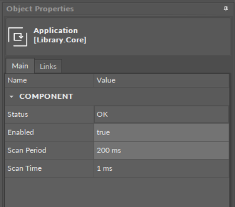
The Application component has the following slots:
-
Status: indicates the current status of the component; if the component works properly, its Status is OK;
-
Available information: Disabled, Fault, OK;
-
-
Enabled: starts and stops execution of the application contained in the component;
-
Scan Period: defines a maximum intended duration of an application cycle; set in milliseconds (ms);
-
Scan Time: an actual time used by the controller to perform a full cycle of an application, read from the CPU; it is desired that the Scan Time is lower than the Scan Period–it means that the application works efficiently and the CPU is not overloaded.
Using Equipment Folders
Good Practice Tip
In future developments, the RAC18-IP controller will have a Haystack functionality implemented in its firmware, which calls for some good practice mechanisms that can be introduced now, with the current functionalities.
The Haystack functionality will offer multiple advantages of using tags–it will help identify parts of equipment controlled by the application and used Data Points, filter data by equipment, sensor, or value, any many more.
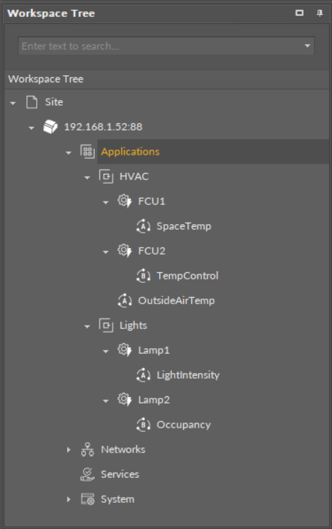
In order to facilitate a future use of the full Haystack functionality, the Equipment component has been included in the Core library. It is therefore recommended to use the following structure when creating applications:
-
Applications container
-
Application component
-
Equipment component
-
Data Point(s)
-
other components
-
-
Equipment component
-
Data Point(s)
-
other components
-
-
-
Such structure will be fully recognized in the Haystack functionality and will require minimum effort to use its full potential once updated.
Difference Between Equipment and Folder Components
The Equipment component with Haystack functionality will allow to identify the types and other characteristics of controlled devices by tags, which will be a main difference between the Equipment and Folder components–the Folder component is merely an organizing component; in the future, it will not carry any Haystack tags functionalities. It is therefore very important to use the Equipment components in the applications structure.
Also refer to: Equipment Manager