Both RS485 and IP I/O modules work with Modbus protocol by default. Protocol configuration can be adjusted by changes on the 4th and 5th bit of the S3 DIP switch according to the table:
|
4 |
5 |
Protocol |
|---|---|---|
|
Off (0) |
Off (0) |
Modbus RTU (in IP modules: Modbus TCP/IP) |
|
Off (0) |
On (1) |
Modbus ASCII |
|
On (1) |
Off (0) |
BACnet master (in IP modules: BACnet IP) |
|
On (1) |
On (1) |
BACnet server |
Protocol selection
Warning!
The BACnet slave mode does not support the discover function.
Modbus TCP/IP
IP I/O modules support up to 4 Modbus TCP clients. If a fifth device wants to connect to the module, the TCP connection will be rejected. In order to secure the module before filling up the call list, a mechanism was introduced as a mechanism for monitoring each of the Modbus TCP connections. There is a parameter called Modbus TCP Communication Timeout (by default, 60 s). If during this time no requests come from the Modbus TCP client, the module closes the connection.
To read the internal registers of the module, the correct Modbus TCP frame needs to be generated with an address according to the setting of a DIP switch. If the address is different, the frame will be sent to the RS485 port.
If the module receives an incorrect Modbus TCP frame, it sends back a frame with error code:
-
0x01 - if the function code in the query is not supported,
-
0x02 - if the address of the register is invalid,
-
0x03 - if in the there is an improper amount of data in the query.
If the query is correct, the device instantly generates an answer with the data or an acknowledgement of the receipt of data, depending on the query.
Free Modbus TCP Sockets Counter
Note:
The free Modbus TCP sockets counter is implemented from the 7.0 firmware.
The counter of free Modbus TCP sockets informs the user about the number of available Modbus TCP connections for the device.
The maximum number of TCP connections is 4.
The number of free Modbus TCP sockets can be reached in two ways:
-
in the 292 Modbus register (read-only): the register shows values from 0 to 4, where 0 means no available connections, 4 means 4 available connections;
-
in the IP Configuration tab in the web server.
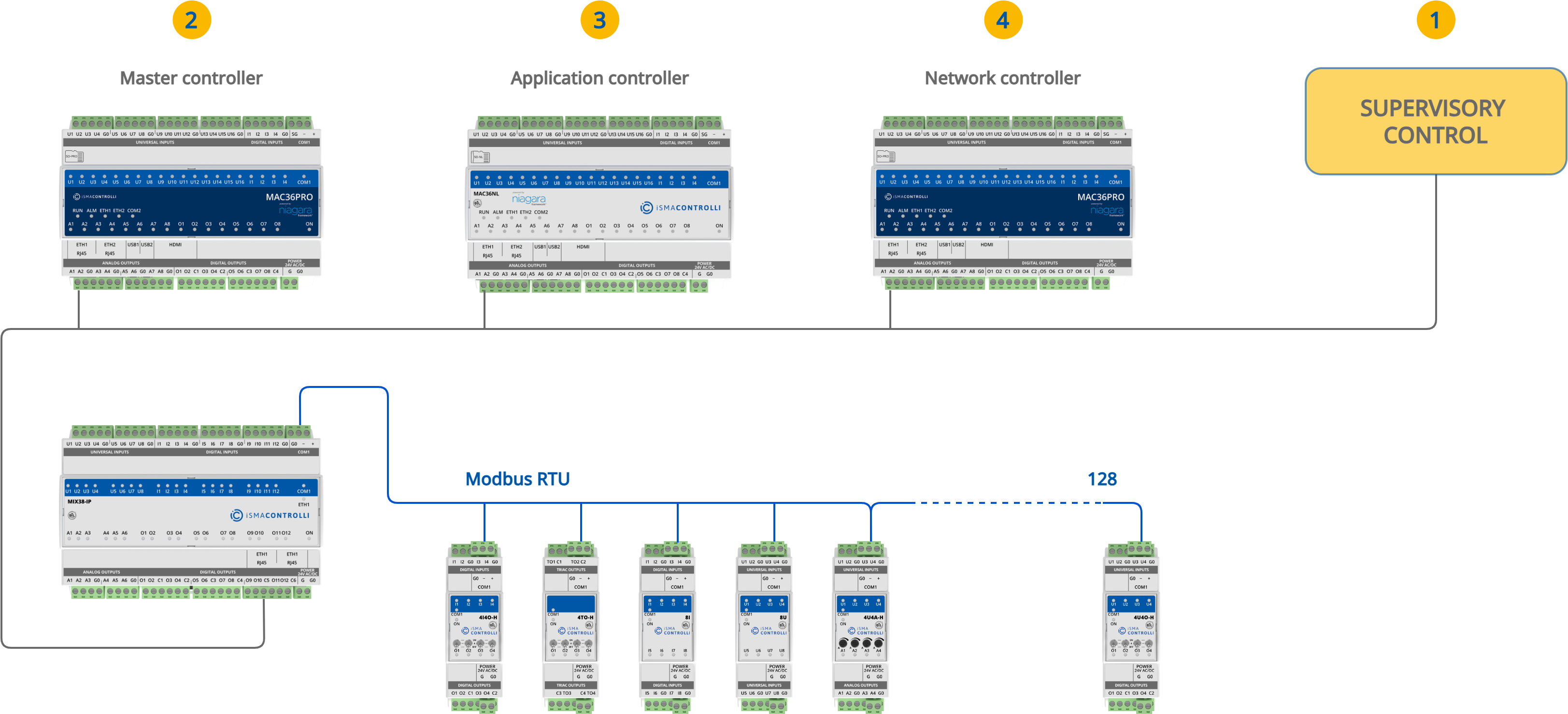
I/O Module as Modbus TCP/IP to Modbus RTU/ASCII Gateway
Multiprotocol IP I/O modules are equipped with a built-in Modbus TCP/IP to Modbus RTU/ASCII gateway, which allows for establishing an RS485 connection with additional I/O modules, or 3rd party Modbus devices. To establish a proper connection, ensure that all RS485 parameters (including baud rate, stop bits, and others) of all the devices connected to RS485 (gateway and additional I/O modules/devices) are properly configured on both client and servers side.
Operation of the gateway is based on a transparent communication. The gateway module checks the Modbus address in the Modbus TCP query. If the address is different from the one set on the DIP switch, the data frame from the query is converted to Modbus RTU/ASCII and sent to the RS485 port. The module waits for an answer from the device connected to the RS485. If the server device answered the correct frame, it is converted to Modbus TCP and sent to the client.
Note: IP I/O modules working in Modbus TCP/IP to Modbus RTU/ASCII gateway mode can still be used as BACnet IP modules.
RS485 Timeout and Modbus Errors
IP I/O module in the gateway function expects an answer within the estimated time. The time is defined by the RS485 Timeout value. The default value is 500 ms and can be adjusted.
If the server RS485 device does not respond within the estimated timeout time, an exception response will be given: error code 0x0B.
While the following error code is received in the BMS system, a query may or may not be repeated according to the settings. For example, in the Niagara Framework, no retry may result in the point going to down mode. To overcome the issue, modules have the ability to block sending the errors information, by enabling/disabling the Send Modbus Errors setting from the built-in web or iSMA Configurator. One the function is disabled, in the absence of any response, the system retries the request according to the settings.
Note: Available from firmware version 7.1, the Send Modbus Errors feature is supported in both IP and RS485 I/O modules. When enabled, the device responds with Modbus Exception Responses as defined in the Modbus standard.
Intermessage Delay
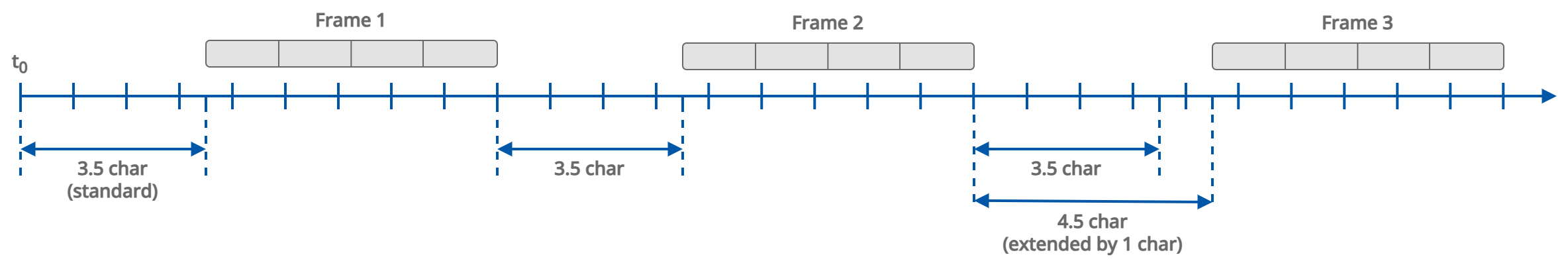
IP I/O modules operating as Modbus gateways offer the possibility to extend the delay between messages sent to the RS485 network. This function ensures compatibility with a wide range of RS485 server devices, including slower or legacy Modbus devices that may not respond correctly to default queries.
The delay is configured using register 139 (40140) and is defined in milliseconds (ms). The default behavior is based on a fixed 3.5 character times delay; however, in some applications, this may be insufficient. Extending the intermessage delay helps prevent communication errors caused by device response limitations.
The setting can be adjusted using the built-in web server or the iSMA Configurator software. The intermessage delay value applies only to IP modules, and has no effect on RS modules, where register 139 (40140) defines the Response Delay.
Note: Please note that the intermessage delay value has to be an integer value.
Calculating the Delay in Milliseconds
To convert character times to milliseconds, use the following formula:
Delay [ms] = (1000 / Baud Rate) x 11 x [Number of Characters]
Where:
-
Baud rate is as configured on the module in the range from 2400 to 115200;
-
11 stands for the total number of bits in the Modbus RTU character;
-
Number of Characters: the number of Modbus RTU characters to calculate the delay for.
Example:
For a 5-character delay at a 9600 baud rate:
Delay [ms] = (1000 / 9600) x 11 x 5 = 5.73 ms ~ 6 ms
Note: New value extends the default 3.5 character delay defined in the Modbus standard.