The article outlines how to connect input and output signals to the iSMA-B-2D device depending on the destination project requirements.
1. General Diagram of the Controller’s Inputs and Outputs
The iSMA-B-2D device has the following inputs and outputs:
-
2 special inputs used to connect presence sensors or light intensity sensor; additionally, the inputs have 24 V DC output to supply sensors.
-
4 digital inputs used to connect light switches and presence sensors for the LLC mode.
-
2 light outputs used to supply DALI ballasts.
The below diagram shows inputs/outputs distribution in the iSMA-B-2D controller.
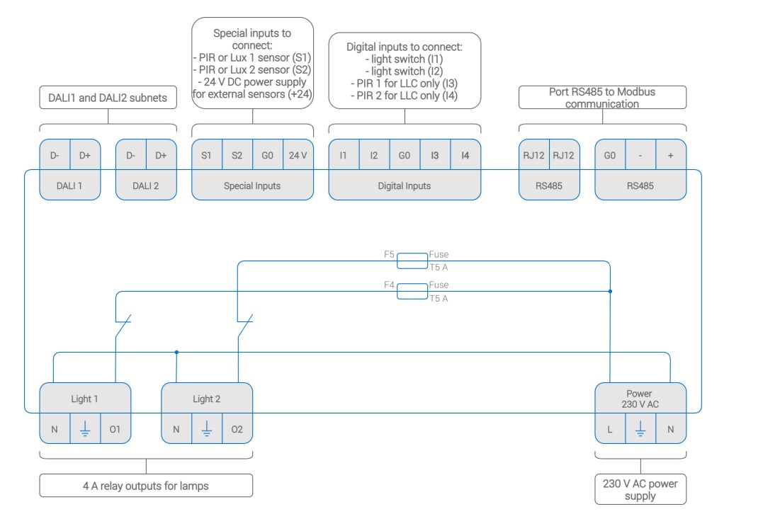
Figure 1. The iSMA-B-2D controller’s inputs and outputs distribution
2. Inputs Connection Diagram and Description
The iSMA-B-2D controller has inputs dedicated for two different purposes. Depending on the selected operating mode (ON/OFF Control, DALI Control, or LLC), the given inputs adjusts its configuration.
2.1 Special Inputs
The S1 and S2 inputs in the DALI mode can be used to connect presence or motion sensors. In the LLC mode, the inputs are used to read the light intensity from the connected sensor. It is possible to use either voltage or current sensors (0-20 mA or 4-20 mA); if the current sensors are used, it is required to use the 200 Ohm resistor . The resistors come with the device.
The S1 input controls the DALI1 network, and the S2 input - the DALI2 network. Inputs have the common 24 V output to supply the sensors. The maximum current load for power supply is 80 mA.
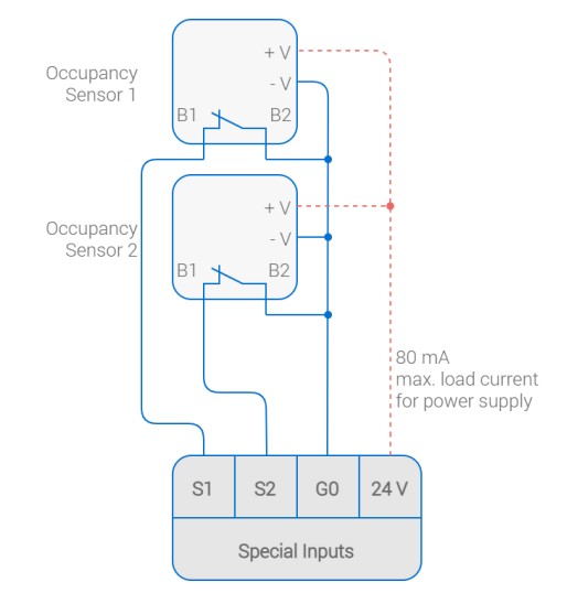
Figure 2. Presence sensors connection diagram
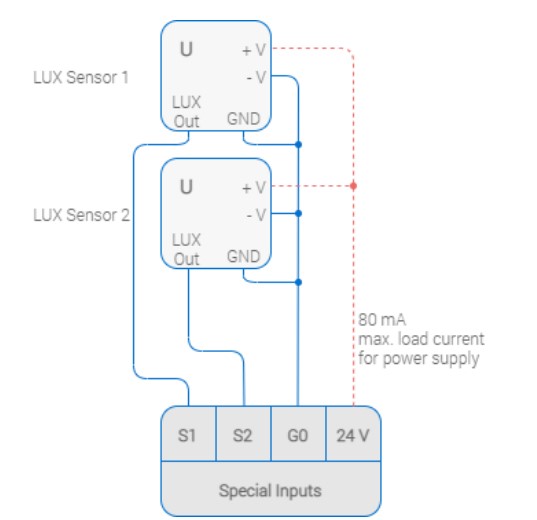
Figure 3. Light intensity voltage sensors connection diagram
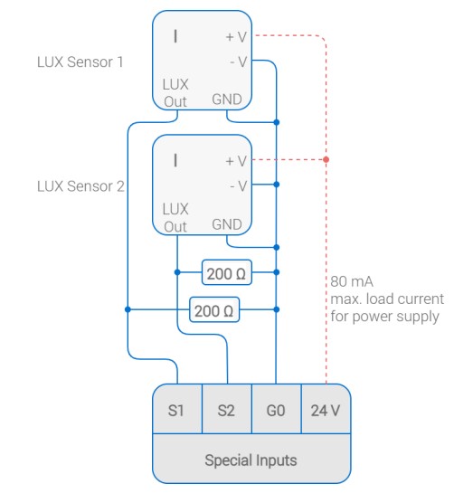
Figure 4. Light intensity current sensors connection diagram
2.2 Digital Inputs
The I1 and I2 inputs can be used to connect light switches. The iSMA-B-2D device controls both monostable and bistable switches. In the LLC mode, the presence sensors can be connected to the I3 and I4 inputs, and, additionally, one presence sensor can be connected to the I3 input and one light switch to the light 2 output.
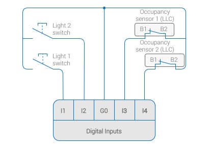
Figure 5. Light switches and two presence sensors connection diagram
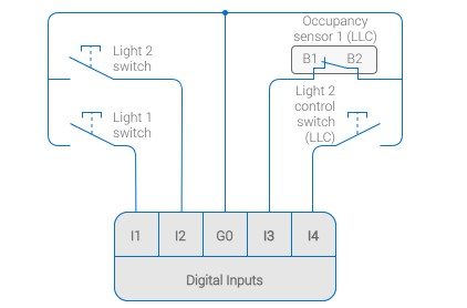
Figure 6. Light switches, presence sensor, and light 2 switch connection diagram
3. Outputs Connection Diagram and Description
The iSMA-B-2D controller has two light outputs, which have different functionalities depending on the selected operating mode (ON/OFF Control or DALI mode). The outputs provide power supply for DALI ballasts directly, no need to use external power supply. The light outputs functionality allows the user to fully control the light using only the iSMA-B-2D device.
Warning! The maximum load for both light outputs and 24 V output on the special inputs is 8 A.
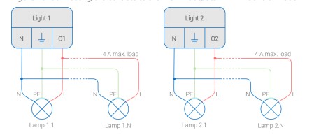
Figure 7. Light outputs connection diagram