Purpose and Description of the Module
The SfAR-S-ETH module is an innovative device converting Modbus TCP into Modbus RTU/ASCII.
The device is equipped with the Ethernet and RS485 interface, 4 digital inputs with counters, and 3 relay outputs. All inputs are insulated from logic using opto-isolators.
The communication with SfAR-S-ETH is via the Modbus TCP protocol. Every received request from the Modbus TCP client is checked considering the address. If the address is different than the SfAR-S-ETH device's address, an automatic conversion of the request frame into the Modbus RTU/ASCII protocol is carried out. Later on, the correctly received answer is sent to the Modbus TCP client.
The usage of a 32-bit processor with ARM core assures fast data processing and smart communication.
A function, called Modbus Device Table, allows the user to define their own enquiries to Modbus RTU/ASCII from the accessible internal registers of the device. This function allows e.g. automatic reading of the statuses of the modules' inputs on the RS485 and inscribing these statuses into the SfAR-S-ETH internal registers. Internal registers are accessible for the Modbus TCP clients without additional delays resulting from using the RS485 bus. This solution strongly accelerates the communication. All the bit orders and registry orders of the Modbus protocol are available.
The module is designed for mounting on a DIN rail in accordance with DIN EN 5002.
The module is equipped with a set of LEDs to indicate the status of inputs and outputs, which is useful for diagnostic purposes and helping to find errors.
Module configuration is done via built-in website or USB by using a dedicated computer program. It also allows for changing the parameters using the Modbus protocol or set the Modbus address using the DIP switches under the front panel.
Technical Specification
|
Power Supply
|
Voltage |
10-38 V DC; 10-28 V AC |
|---|---|---|
|
Power consumption (with active Modbus transmission, all outputs on and high state on all inputs) |
7 W at 24 V DC |
|
|
9 VA at 24 V AC |
||
|
Digital inputs
|
No. of inputs |
4 |
|
Voltage range |
0-36 V |
|
|
Low state "0" |
0-3 V |
|
|
High state "1" |
6-36 V |
|
|
Input impedance |
4 kΩ |
|
|
Isolation |
3650 Vrms |
|
|
Inputs type |
PNP or NPN |
|
|
Counters
|
No. |
4 |
|
Resolution |
32-bit |
|
|
Frequency |
1 kHz (max.) |
|
|
Pulse width |
500 µs (min.) |
|
|
Relay Outputs
|
No. of outputs |
3 |
|
Maximum current and voltage (resistive load) |
3 A 230 V AC |
|
|
3 A 30 V DC |
||
|
Temperature
|
Work |
-10°C to +50°C (14°F to 122°F) |
|
Storage |
-40°C to +85°C (-40°F to 185°F) |
|
|
Connectors
|
Power supply |
2 pin |
|
Communication RS485 |
3 pin |
|
|
Communication Ethernet |
RJ45 |
|
|
Inputs and outputs |
2 x 5 pin |
|
|
Quick connector |
IDC10 |
|
|
Configuration |
mini USB |
|
|
Size
|
Height |
119.1 mm (4.689 in) |
|
Length |
110.8 mm (4.362 in) |
|
|
Width |
22.7 mm (0.894 in) |
|
|
Interface |
Ethernet |
10/100 Mbps |
|
RS485 |
Up to 128 devices |
Technical specification
Dimensions
The appearance and dimensions of the module are shown below. The module is mounted directly to the rail in the DIN industry standard. Power connectors, communication and IOs are at the bottom and top of the module. USB connector configuration and indicators are located on the front of the module.
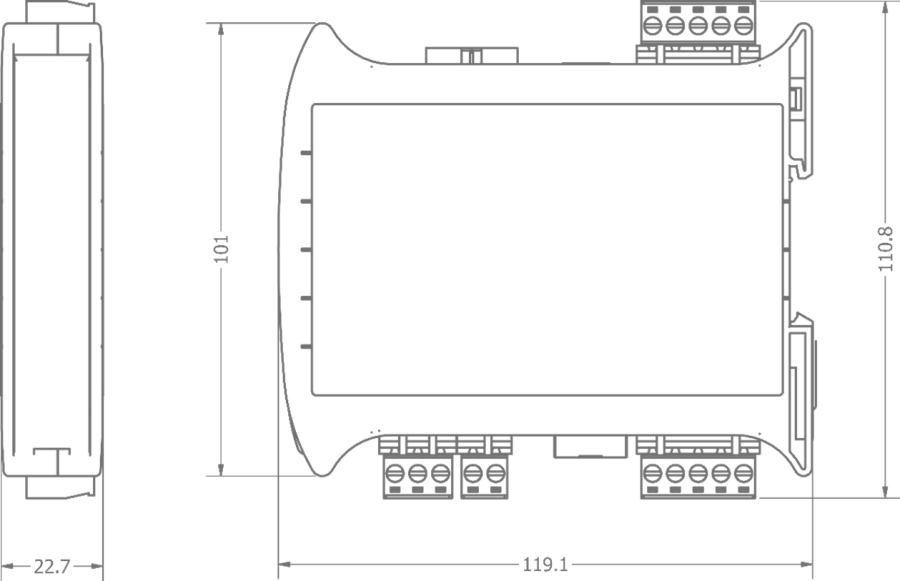
Dimensions