This article describes how special applications built into some MINI series modules work. They were created to enable the user to use modules to control simple processes without the need to create advanced logic. Input number 1 affects output number 1, input number 2 affects output number 2, etc. It is not possible to change the input-output correlation. Below each application description are examples of their use.
1. Monostable relay
In this mode, the occurrence of a rising or falling edge will change the output state. The application can be run remotely by changing the COMMAND register (40020). The outputs can also be controlled independently, e.g. from the BMS system level using the DIGITAL OUTPUTS register (40018).
The application can be used as a toggle button to control lighting.
The application is available for the following modules: iSMA-B-4I4O-H, iSMA-B-4I4O-H-IP, iSMA-B-4U4O-H, and iSMA-B-4U4O-H-IP.
2. Bistable relay
In this mode, only a rising edge will cause the output to change. The application can be run remotely by changing the COMMAND register (40020). The outputs can also be controlled independently, e.g. from the BMS system level using the DIGITAL OUTPUTS register (40018).
The application can be used as a bell button to control lighting. The main advantage of the application is the ability to integrate the application into the BMS without creating logic.
The application is available for the following modules: 4I4O-H, 4I4O-H-IP, 4U4O-H, and 4U4O-H-IP.
3. Time relay NO [ms] or [s]
In this mode, only a rising edge will cause the output to change. It is not possible to change the input-output correlation. The time value is defined by the TIME VALUE * register. The outputs can also be controlled independently, e.g. from the BMS system level using the DIGITAL OUTPUTS register (40018). The application can read the time from the TIME VALUE register in milliseconds or seconds, this mode can be changed with the OPERATION MODE ** register.
The application can be used in hotel facilities, e.g. to switch lights in the corridor depending on the motion sensor. Detection of presence in the corridor by the motion detector may turn on the light and maintain the lighting for a set time.
The application is available for the following modules: 4I4O-H, 4I4O-H-IP, 4U4O-H, and 4U4O-H-IP.
4. NC time relay [ms] or [s]
In this mode, only the occurrence of a falling edge at the input will cause the output state to change. Changing the state of the input from high to low starts the timer during which the output remains high. The time value is defined by the TIME VALUE * register. The outputs can also be independently controlled, e.g. from the BMS system level using the DIGITAL OUTPUTS register (40018). The application can read the time from the TIME VALUE register in milliseconds or seconds, this mode can be changed with the OPERATION MODE ** register.
The application can be used, for example, to lower window blinds depending on the presence of the card in the "card holder". Removing the card from the "card holder" may activate the motor responsible for lowering the roller shutter. The time needed to fully lower the roller shutter should be entered in the "Time Value" register.
The application is available for the following modules: 4I4O-H, 4I4O-H-IP, 4U4O-H, and 4U4O-H-IP.
5. Input forwarding
In this mode, the input value is transferred directly to the output.
The application can be used, for example, to switch on the electricity in the room based on the presence card reader. The presence of the card in the reader causes the power to be turned on, the lack of presence means the lack of power. Additionally, the presence of the card in the sensor can be monitored by the BMS system, without creating any logic.
The application is available for the following modules: 4I4O-H, 4I4O-H-IP, 4U4O-H, and 4U4O-H-IP.
6. Heating
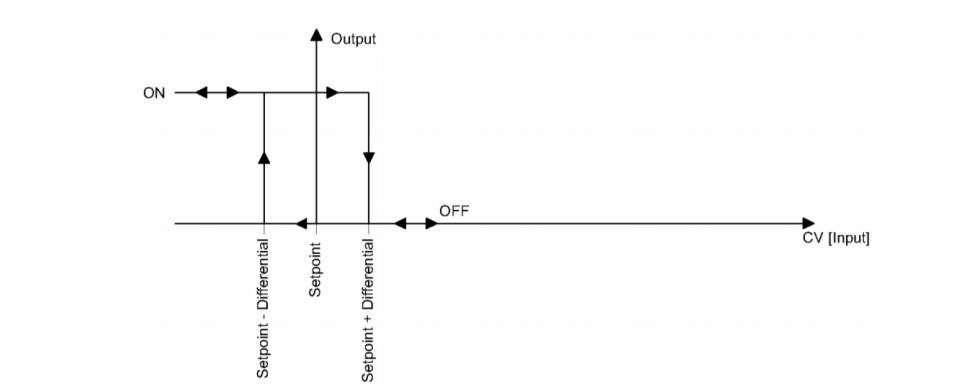
In this mode, the output is controlled like a classic thermostat based on the SETPOINT, CONTROL VALUE and DIFFERENTIAL registers. If the input value is lower than or equal to the difference of values in the SETPOINT and DIFFERENTIAL registers, the output state is high. If the input value is greater than or equal to the sum of the values in the SETPOINT and DIFFERENTIAL registers, the output state is low.
Low output:
Control value> = Setpoint + Differential
High output:
Control value <= Setpoint - Differential
The application operation algorithm is shown in the diagram below:

Picture 1. Operation of the algorithm for the heating mode.
NOTE: If the temperature sensor connected to the input fails or is disconnected, the heating mode is inactive and the output goes low.
7. Cooling
In this mode, the output is controlled like a classic thermostat based on the SETPOINT, CONTROL VALUE and DIFFERENTIAL registers. If the value on the input is lower than or equal to the difference of values in the SETPOINT and DIFFERENTIAL registers, the output state is low. If the input value is greater than or equal to the sum of the values in the SETPOINT and DIFFERENTIAL registers, the output state is high.
Low output:
Control value <= Setpoint - Differential
High output:
Control value> = Setpoint + Differential
The application operation algorithm is shown in the diagram below:

Picture 2. Operation of the cooling mode algorithm.
NOTE: If the temperature sensor connected to the input fails or is disconnected, the heating mode is inactive and the output goes low.
*TIME VALUE - this register for individual inputs has the following address: DI1 (40177), DI2 (40181), DI3 (40185), DI4 (40189).
** OPERATION MODE - this register for individual inputs has the following address: DI1 (40176), DI2 (40180), DI3 (40184), DI4 (40188).
