The article outlines the DIP switch configurations available for project requirements in the iSMA-B-2D device.
1. CFG DIP Switch
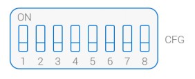
The iSMA-B-2D controller has an 8-position CFG DIP switch for configuration of the controller’s application according to the project requirements.

1.1 First CFG DIP Switch
The first CFG DIP switch is used to select the type of the switches connected to I1 and I2 digital inputs.
-
monostable switches - OFF;
-
bistable switches - ON.
1.2 Second CFG DIP Switch
The second CFG DIP switch defines how many light zones are controlled by the switch connected to the I1 input.
-
the I1 switch controls only one zone - OFF;
-
the I1 switch controls two zones - ON.
1.3 Third CFG DIP Switch
The third CFG DIP switch defines how many light zones are controlled by the PIR sensor connected to the S1 input.
-
the S1 switch controls only one zone - OFF;
-
the S1 switch controls two zones - ON.
1.4 Fourth CFG DIP Switch
The fourth CFG DIP switch defines how many light zones are controlled by the switch connected to the I2 input.
-
the I2 switch controls only one zone - OFF;
-
the I2 switch controls two zones - ON.
1.5 Fifth CFG DIP Switch
The fifth CFG DIP switch defines how many light zones are controlled by the PIR sensor connected to the S2 input.
-
the S2 switch controls only one zone - OFF;
-
the S2 switch controls two zones - ON.
1.6 Sixth CFG DIP Switch
The sixth CFG DIP switch selects the application, which the iSMA-B-2D device executes.
-
DALI Light Control application - OFF;
-
ON/OFF Light Control application - ON.
Warning! Switching the eighth CFG DIP switch to the ON position turns off the sixth DIP switch functioning.
1.7 Seventh CFG DIP Switch
The seventh CFG DIP switch is not used.
1.8 Eighth CFG DIP Switch
The eighth CFG DIP switch selects the application, which the iSMA-B-2D device executes.
-
application defined by the sixth CFG DIP switch - OFF;
-
Light Level Control application - ON.
2. Protocol DIP Switch
The iSMA-B-2D device has a 6-position Protocol DIP switch, which defines the RS485 communication baud rate, type of communication protocol, and restores default settings.
2.1 First Three Protocol DIP Switches
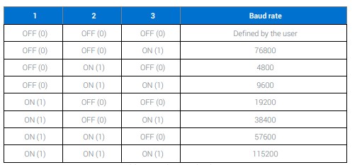
First three Protocol DIP switches are used to define the RS485 communication baud rate according to the table below.

Table 1. Selecting communication baud rate
2.2 Fourth and Fifth Protocol DIP Switches
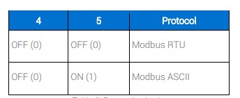
The iSMA-B-2D controller can communicate using the Modbus RTU and Modbus ASCII communication protocols. Using the fourth and fifth DIP switches defines, which protocol is used, according to the table below:

Table 2. Selecting communication protocol
2.3 Restoring Default Settings
The sixth Protocol DIP switch is used to restore default settings.
Warning! Performing the action described below results in restoring default settings to all registers.
The process of restoring default settings in the iSMA-B-2D device is described in the following steps:
-
Turn off the controller’s power supply.
-
Set the sixth Protocol DIP switch to ON.
-
Turn the power supply on and wait until the ON LED diode starts blinking.
-
Set the sixth Protocol DIP switch to OFF.
3. MAC DIP Switch
The iSMA-B-2D controller has an 8-position MAC DIP switch, which define the Modbus address. The address is set according to the table below:
|
Dip Switch No. |
Position |
Function |
|
1 |
On |
Add 1 to Address |
|
Off |
Add 0 to Address |
|
|
2 |
On |
Add 2 to Address |
|
Off |
Add 0 to Address |
|
|
3 |
On |
Add 4 to Address |
|
Off |
Add 0 to Address |
|
|
4 |
On |
Add 8 to Address |
|
Off |
Add 0 to Address |
|
|
5 |
On |
Add 16 to Address |
|
Off |
Add 0 to Address |
|
|
6 |
On |
Add 32 to Address |
|
Off |
Add 0 to Address |
|
|
7 |
On |
Add 64 to Address |
|
Off |
Add 0 to Address |
|
|
8 |
On |
Add 128 to Address |
|
Off |
Add 0 to Address |
Table 3. Setting the device’s address
For example, in order to set the 73 address, set the seventh, fourth, and first Protocol DIP switch to ON:
73 = 1 + 8 + 64.
