General Description
This chapter describes the user interface of the iC Actuator Configurator, which is suitable to configure and monitor the MVC-2-RS, MVE-2-RS, and EBV family.
To interface with the devices, RS485 or USB communication port can be used.
Note: In USB connection mode functionality connected to motor drive are not applicable in USB connection mode, it is not possible, for example, to set a command signal to move the actuator or view the graphs of the real-time actuator position.
Main Page Description
To open the configurator, it is necessary to select the icon in the windows menu
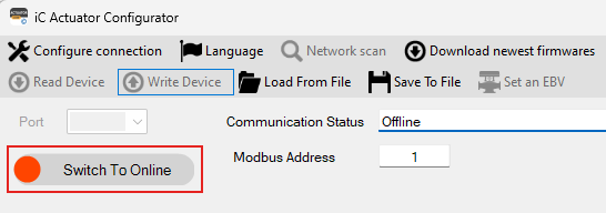
The configurator will start in Offline mode:
In this status (Offline), the user can:
-
Configure Master (Serial Converter) Connection:
-
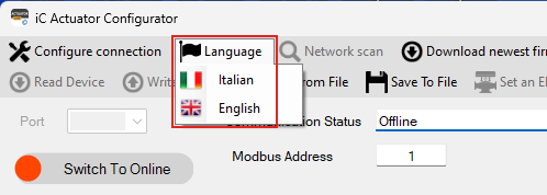
Change Language (Italian or English)
-
Load Configuration File
-
Save Configuration File
-
Download the newest firmware from the server
Set Modbus Address (Slave)
-
Switch To Online Mode
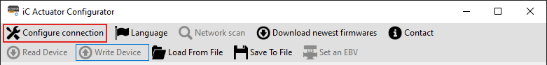
Configure Connection (Master)
This button is used to define the Modbus connection options of the iSMA-B-CVT-RS485 converter. If the user intends to change the Modbus connection options, the parameters have to be changed before clicking the toggle button to connect to the actuator.
In case of using a different serial converter, in some cases, it is necessary to identify the right COM port following the procedure described below.
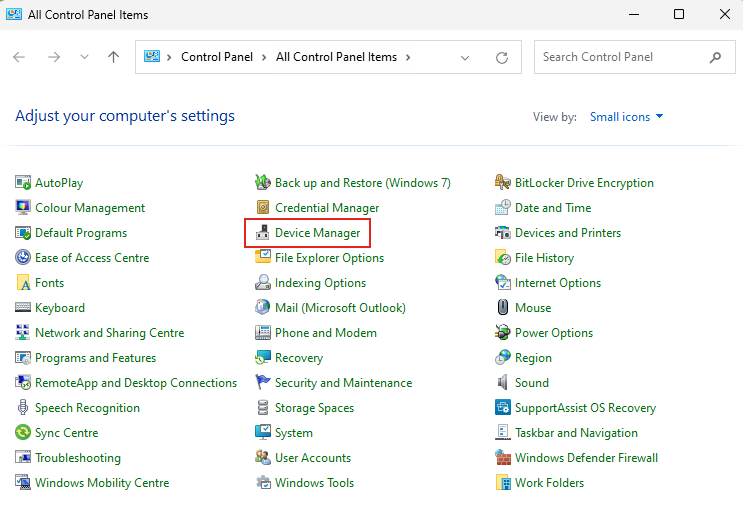
In the upper area of the main window, there is a drop-down list that displays the COM port currently in use by the PC. To identify the number of the serial port (COM Port), which the USB-RS485 converter is connected to, it is necessary to access the PC Control Panel and select the Device Manager:
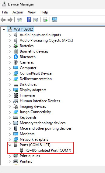
Select the Ports (COM and LPT) field to check the serial port number to which the serial converter is connected (COM7 in the example below).
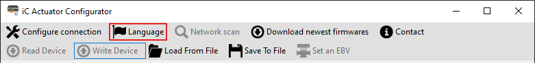
Language
This button is used to change the language of the configurator.
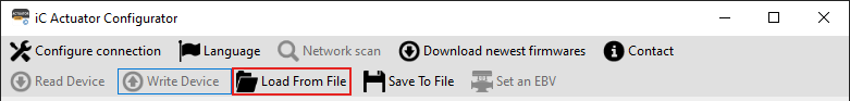
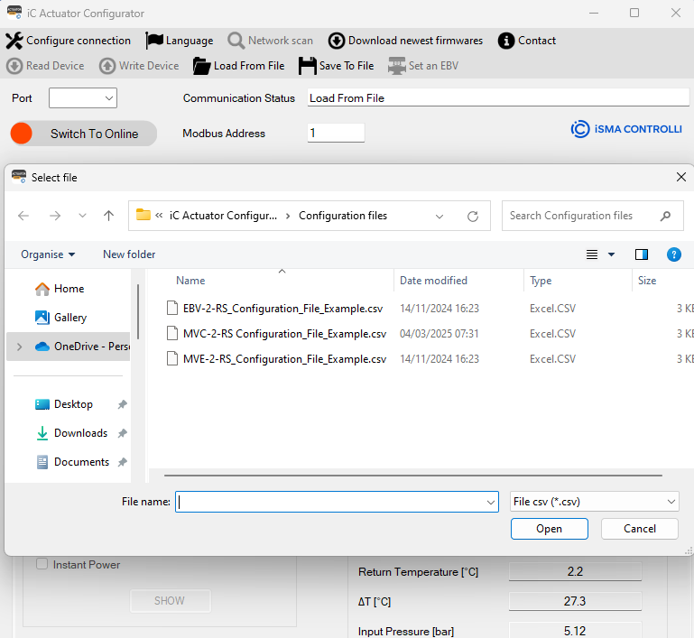
Load From File
This button is used to load a .csv file with actuator parameters.
The configuration files are placed in a dedicated directory:
C:\Program Files (x86)\iC Actuator Configurator\Configuration Files
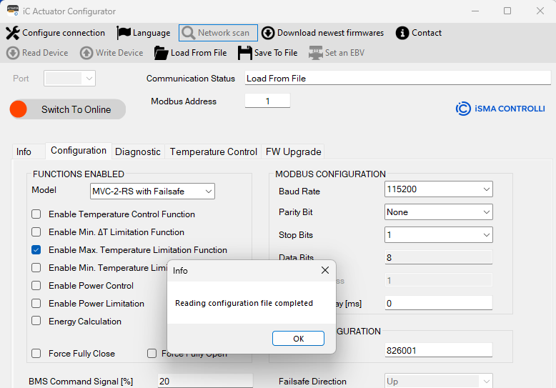
If the configuration file is loaded correctly, the following message box will appear:
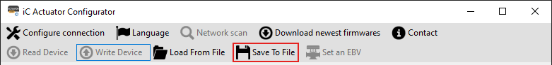
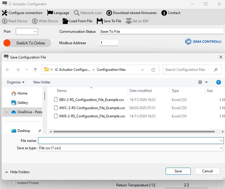
Save To File
This button is used to save a .csv file with actuator parameters prepared in Offline Mode.
The configuration files should be placed in a dedicated directory:
C:\Program Files (x86)\iC Actuator Configurator\Configuration Files
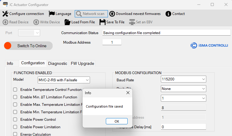
If the configuration file is saved correctly, the following message box will appear:
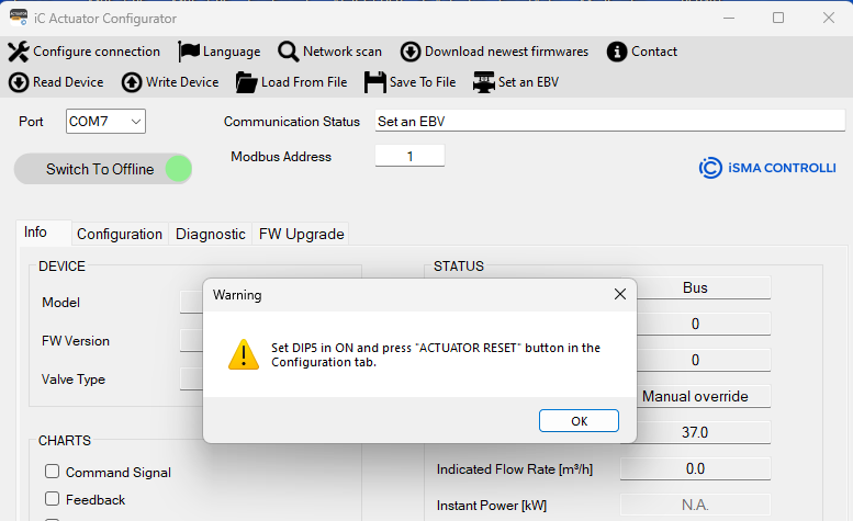
Set an EBV
This button is used to configure the EBV actuator starting from MVE-2-RS or starting from EBV to change in another EBV model.
To use this function is necessary to have MVE-2-RS model (MVE515X-2-RS or MVE215X-2-RS) and switch ON DIP5.
In case the DIP5 is off, the tool will advise the customer to set the DIP and perform a reset.
After reset the actuator is automatically configured as an EBV065-024-010, now it is possible to configure the desired EBV actuator by selecting the proper configuration file (automatically it will open directory related to current model):
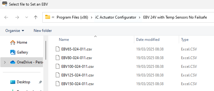
If actuator is an EBV, to change it in another EBV model is always necessary to move DIP5 in ON and finally to select the proper configuration file (based-on the current EBV model, clicking on “Set an EBV” option will be opened the folder with configuration files related to the current model).
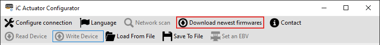
Download the newest firmware
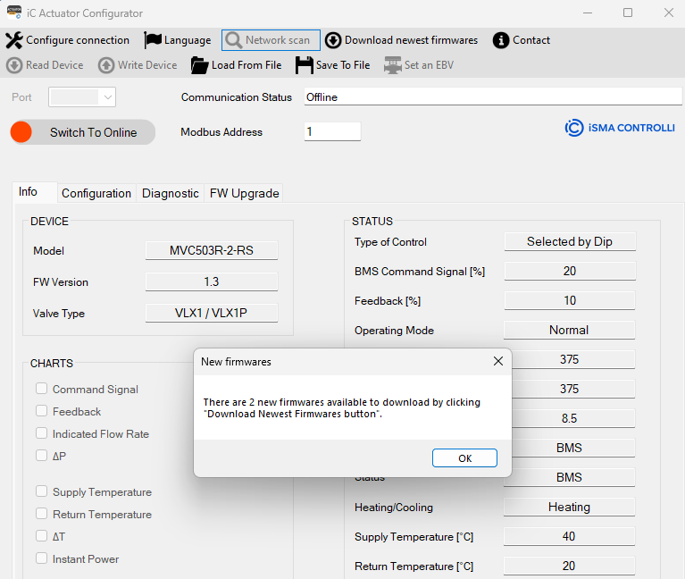
This button is used to check if new versions of firmware are available on the server.
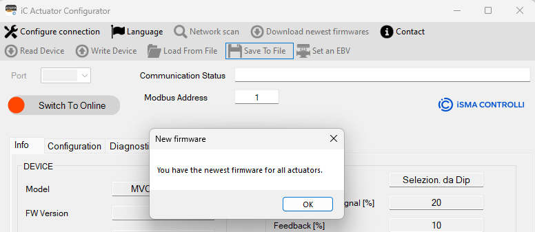
The iC Configurator, at the startup, advises the user if new firmwares are available on the server with the following message box:
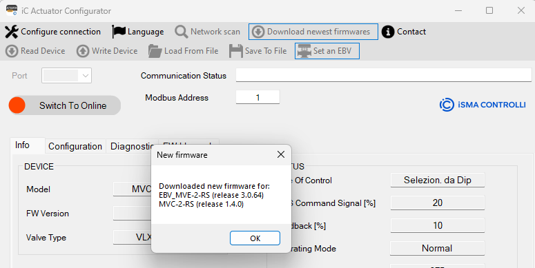
If new firmware is available, it is possible to download the latest release by clicking on the Download newest firmware button:
If after clicking on the Download newest firmware button, no new firmware is available, the message box will show the following message:
The new firmware will be placed in the following local folder, and they can be used in the FW Upgrade process.
C:\Users\nomeutente\AppData\Roaming\iSMA CONTROLLI S.p.A\iC Actuator Configurator\1.0.0.0\Firmware
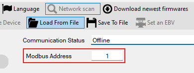
Set Modbus Address (Slave)
The textbox shows the Modbus address of the device, to which the Configurator will send all the command/operations. By default, the address is set to 1.
Check Communication Status
The textbox shows the Communication Status.
The following status can be detected:
-
Device not found (Master Serial Port not available)
-
Waiting for connection (waiting for proper COM PORT)
-
RS485 converter detected (Master Serial Port detected)
-
Waiting for COM port selection (waiting to select proper COM PORT)
-
Offline (the device is not connected)
-
Online (the device is connected and ready)
-
OK (communication is ok)
-
Reading data from the device in progress (the configurator is reading the device)
-
Reading data from the device terminated (the configurator read the device)
-
Writing data into the device in progress (the configurator is writing device)
-
Reading data from the device terminated (the configurator wrote the device)
-
Slave Device Timeout (device not responding)
-
Actuator reset in progress (device reset)
In case of using USB connection, the following Status can be detected:
-
Device attached (actuator connected via USB)
-
Device removed (actuator disconnected via USB)
-
Device not found (actuators not found in USB port)
-
The attempt to read an Input report has failed (USB communication error)
-
An Output report has been written (USB communication error)
-
The attempt to write an Output report failed (USB communication error)
-
An Input report has been read (USB communication error)
-
The attempt to read an Input report has failed (USB communication error)
-
Device not connected (actuator not detected via USB)
-
No device detected (actuator not detected via USB)
-
ERROR (3) - N. of bytes requested by the Host is different from Device response (USB communication error)
-
The received packet does not contain the termination (USB communication error)
-
ERROR (16) - Different starting address between request and received packet (USB communication error)
-
ERROR (16) - Number of registers to write different from the request (USB communication error)
-
The received packet does not contain the termination characters (USB communication error)
-
Data received without termination sequence. Retry please. (USB communication error)
Select Communication Port
If the serial converter is already connected at startup, only the relative COM port is automatically detected.
Switch to Online Mode
In Online mode, it is possible to read the devices connected to the network.
After the toggle button is clicked, the tool will advise the user to save the configuration (if changed) in the configuration file:
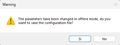
The user can skip this message by selecting “NO” or save the configuration in a proper file by selecting “YES”.
After this operation, the tool automatically recognizes the COM port, and it will perform a first reading of the device with the Modbus Address selected before.
In case of multiple COM ports, the tool advises the user
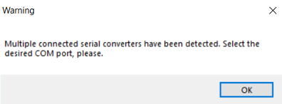
After this message, it’s necessary to click on COM Port ComboBox and select the desired COM Port and the connection will start automatically.
If the device is recognized, the following functionality functionalities are available:
Read Device
This button allows the user to read all parameters from the selected device and update the values in all tabs of the Configurator.
Write Device
This button allows the user to write into the device all the parameters defined in the Configurator.
WARNING! To read a parameter inside the tab, it is necessary to click the corresponding label.
To write a parameter inside a textbox, it is required to press “Enter” key after a new value is entered or after selecting an item from a dropdown menu
Network Scan
With this function, it is possible to check devices connected to the Communication Port and check the main parameters of the devices.
To use this function, it is necessary to set the Start and End Modbus address and click READ.
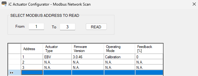
The following information is available after the network scan:
-
Actuator Type: Actuator family name
-
Firmware Version: Firmware installed on selected actuator
-
Operating Mode: Define the operating mode of the actuator (including Errors, it will show the error code between round brackets).
-
Feedback: Actuator Position.
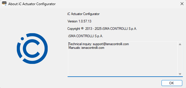
Contact information
This button is used to check the main information about:
-
Configurator Name
-
Software Release
-
Company Name
-
Web address for technical support and manual
Tabs Description
The following tabs can be used both for creating a configuration file and for checking and configuring the main parameters of the connected devices.
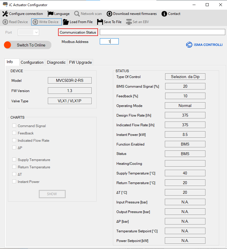
Info Tab
In this window, it is possible to read the main information about the actuator:
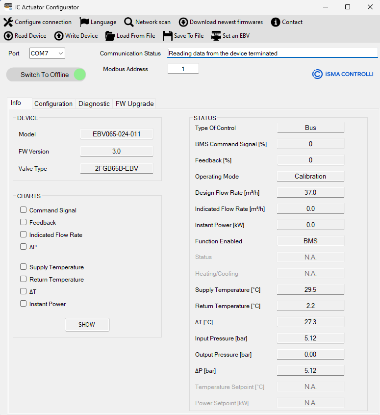
In this area, the following information is visible:
-
Model: represents the Product Part Number. The alphanumeric code is composed as follows:
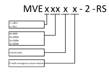
An example of the code is the following: MVE506-2-RS, which represents an IC ACTUATOR model with 600 N of force, powered with 24 V AC Modbus/BACnet communication without emergency return.
The value cannot be changed in the Configurator.
-
FW Version: identifies the current version of the firmware installed on the actuator.
-
Valve Type: show the current valve connected to the actuator.
STATUS Information
-
Type of Control shows the command type for the actuator (the default value is 0-10 V, selectable by DIP switch)
-
BMS Command Signal [%]: shows the current Modbus command signal value (between 0-100%).
Note: It is a read-only value. The BMS command is set in the Configuration tab.
-
Feedback [%]: allows to identify the position of the actuator in the 0-100% range of the stroke.
-
Operating Mode: shows the operating status of the actuator, which can be one of the following:
-
Normal: the actuator is working following the command signal at its input; therefore, it is not in the initial positioning, calibration, emergency return, or manual override phases.
-
Initial positioning: the actuator is moving towards the initial position determined by the DIP 1 or, if the DIP switches are disabled, based on the action type value set in the Configuration tab.
-
Calibration: the actuator is calibrating the stroke.
-
Error: indicates that one or more errors have occurred; the details of the error are visible in the Errors section of the Diagnostics tab.
-
Manual override: shows that the manual command has been enabled; the actuator does not respond to the command signal until the manual override is disengaged and the initial positioning ends.
-
Fail-safe: shows that the actuator is in the emergency return phase due to the lack of power supply. This operative mode is available only for the emergency return models.
-
-
Design Flow Rate [m3/h]: this value (read only) represents the maximum desired flow rate.
-
Indicated Flow Rate [m3/h]: this value (read only) represents the flow rate calculated as a function of the valve position and the valve flow characteristic.
-
Instant Power [kW]: represents the current power. It is shown only if the selected valve is a PICV and if the temperature sensors work properly.
-
Function enabled: show which of the following functions are enabled:
-
BMS.
-
Temperature Control.
-
∆T limit.
-
Temp Limit.
-
Temp Limit.
-
Power Control.
-
Power Limit.
-
-
Status: shows if the limit function is active or not in real time.
-
Heating/Cooling: shows whether the heating or cooling control mode is active.
-
Supply Temperature [°C]: represents the temperature value, in °C, detected by the supply temperature sensor (it is the sensor connected to the T1 input of the terminal block). It is a read-only value.
Note: If a value of 500.0 is displayed, it means that the supply sensor (T1) is disconnected or faulty. In case of functions which require that temperature sensors are enabled, this error condition is also highlighted in the Diagnostics tab. In case a temperature sensor anomaly occurs, all the related functionalities are disabled.
-
Return Temperature [°C]: represents the temperature value, in °C, detected by the sensor positioned at the valve outlet port (it is the sensor connected to the T2 input of the terminal block). It is a read-only value.
Note: If a value of 500.0 is displayed, it means that the return sensor (T2) is disconnected or faulty. In case of functions which require that the temperature sensors are enabled, this error condition is also highlighted in the Diagnostics tab. In case a temperature sensor anomaly occurs, all the related functionalities are disabled.
-
∆T [°C]: shows a difference between the supply and return temperature value in °C.
Note: If the temperature sensors have problems or are not connected, 500.0 is displayed.
-
Temperature Setpoint [°C]: shows a setpoint configured for the temperature control enabled function.
-
Power Setpoint [kW]: shows a setpoint configured for the power control enabled function.
-
CHARTS: by checking the items listed in this section, it is possible to view the charts of the desired variables. The graphs are grouped into 2 types: the Control charts (command signal, feedback, indicated flow rate) and the Temperature and Power charts (supply temperature, return temperature, delta T, instant power). Clicking the CHARTS button, a window will appear with selected charts. The 2 types of variables are represented in 2 different graphic areas (see the figure below).
WARNING! The CHARTS functionality is NOT available when connected actuator is an EBV or a MVE-2-RS and the connection is USB (the chart options are disabled).
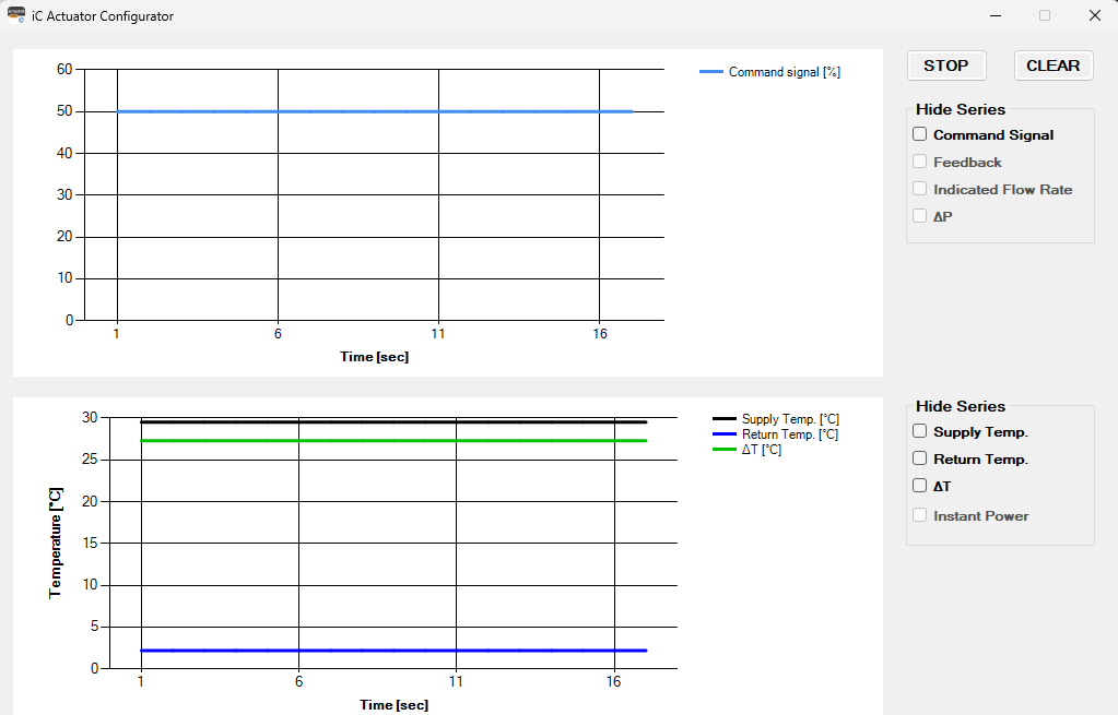
The window shows the 2 areas for the 2 types of charts described above. The charts displayed are those selected in the Info tab, and they are updated every second starting from the opening of the window in the specific chart area.
It is possible to stop updating charts and display them by clicking the STOP button and resume updating by clicking the START button (the same button, therefore, allows you to stop or restart the display). When the update is resumed, the first data displayed will be the current one and not the one at the time of the stop (therefore, the data will be lost during the time the chart stops).
It is possible to hide one or more plotted graphs from the display by marking checkboxes in the Hide series section (the series is hidden, but the acquired data continues to be stored anyway).
It is again possible to show the previously hidden graphs by removing the check mark from the specific box; as mentioned, the graphs will show a temporal continuity in the data even if they are hidden.
The CLEAR button allows the user to delete the graphs from the display area.
After 90 minutes, the charts are no longer updated because the maximum amount of data that can be displayed has been reached. A pop-up message warns the user and asks if the data should be saved to a file (.csv); if the action is confirmed with the Yes button, a window is opened for saving the file, and, once the name of the file is indicated, the charts in the two areas are deleted. By clicking the No button, the data are not saved to the file, and the charts will be deleted. By clicking the START button, it is possible to restart the data display from the current instant.
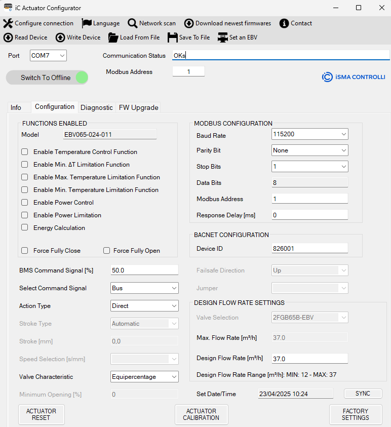
Configuration Tab
In this window, it is possible to set the following actuator's configuration parameters:
-
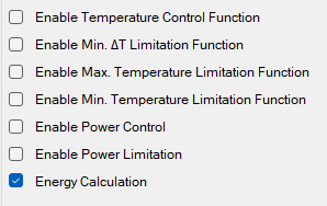
FUNCTIONS ENABLED: to select the available functions for the actuator model.
- Temperature Control Function: the function constantly overrides the control signal to maintain the set temperature or ΔT by closing or opening the valve.
- ∆T Limitation Function: the actuator is controlled by the input signal (voltage or current control) or by the Modbus/BACnet command, but if the ∆T goes below the temperature limitation set (heating or cooling), the actuator overrides the command, closing the valve.
- Temperature Limitation Function: the actuator is controlled by the input signal (voltage or current control) or by the Modbus/BACnet command but, if the temperature exceeds the temperature limitation set (heating or cooling), the actuator:
-
opens the valve in cooling,
-
closes the valve in heating.
- Min Temperature Limitation Function: the actuator is controlled by the input signal (voltage or current control) or by the Modbus/BACnet command but, if the temperature goes below the temperature limitation set (heating or cooling), the actuator:
-
closes the valve in cooling,
-
opens the valve in heating.
- Power Control: the actuator calculates the thermal power transferred from the coil and controls it. This function is enabled when the actuator is installed on a PICV valve (iC or custom) and both temperature sensors are installed on the actuator.
- Power Limitation: the actuator limits the opening of the valve when the calculated power is greater than a Max Set value. This function is enabled when the actuator is installed on a PICV valve (iC or custom) and both temperature sensors are installed on the actuator.
- Energy Calculation: the actuator calculates the instantaneous thermal power and energy (heating/cooling) supplied by the controlled coil. This function is enabled when the actuator is installed on a PICV valve (iC or custom), both temperature sensors are connected to the actuator, and the date and hour are synchronized.
-
BMS Command Signal [%]: allows to set the Modbus/BACnet command for positioning the actuator between 0-100% (0.1% step). To send the command to the actuator, press the Enter key on the keyboard.
-
Select Command Signal: allows to select the type of command signal for driving the actuator (by default set to 0-10 V, selected by DIP switches).
-
Action Type: if Modbus/BACnet is enabled, this menu allows the user to select the action type of the actuator (direct or reverse). To write the selected value into the actuator, press the Enter key on the keyboard.
-
Valve Characteristic: it is possible to select the characteristic of the valve: linear or Equi percentage (EQP).
-
Minimum Opening [%]: represents the minimum opening valve (expressed as a percentage) necessary to ensure a minimum flow in the system.
Note: to save a specific value in the actuator, it is required to press Enter key on the keyboard. To save all data, it is possible to click the Write Device option.
-
Jumper: it used to select if the emergency return direction is determined by the jumper on the emergency return board (enabled) or by the Modbus or by BACnet. This is enabled for the emergency models only.
-
Failsafe Direction: allows to select the emergency return direction (up or down) if the Enable Jumper function is disabled. This is enabled for the emergency models only.
-
MODBUS CONFIGURATION: it used to set the Modbus configuration parameters of the actuator, in particular:
-
Baud Rate: 9600, 19200, 38400, 57600, 76800 and 115200.
-
Parity Bit: sets the parity bit to none, odd, or even.
-
Stop Bits: 1 or 2.
Note: The factory settings of the actuator are a baud rate 115200, no parity bit, and 1 stop bit.
-
Modbus Address: used to set the Modbus address of the actuator.
Note: To write the value in the actuator, press “Enter” on the keyboard after selecting the desired value.
-
BACNET CONFIGURATION: allows to configure/read the BACnet Device ID.
-
DESIGN FLOW RATE SETTING:
-
Valve Selection: used to select the valve connected with the actuator, in this case VLX6P.
-
Max Flow Setting: used to select the maximum flow, in this case 5.
-
Design Flow Rate [m3/h]: show the maximum desired flow rate, in this case 10.
-
Design Flow Rate Range [m3/h]: show the range of design flow rate based on the max flow setting configurated, in this case 2.8-11.0.
-
Set Date/Time: when the Configurator is Online and the tab Configuration is selected, the textbox displays automatically the current date and time of the PC are saved in the actuator. At the same time, the clock error displayed in the Diagnostics tab disappears. Each time the actuator turns off (the error condition is indicated in the Diagnostics tab), the date and time must be synchronized. If date and time are not updated after Configuration tab is selected, press “SYNC” button.
Note: By clicking on the Actuator Date/Time label, the date and time inside the actuator is read and displayed in the textbox.
-
Actuator Calibration: forces the calibration of the actuator stroke.
-
Actuator Reset: performs a software reset of the actuator.
-
Factory settings: restore factory values to the actuator reload. This action overwrites the configuration and data inside the actuator.
The variables in this window are read from the actuator and displayed when the Read Device item is clicked from the dropdown menu. It is also possible to invoke an instant reading of a textbox by clicking on the corresponding label.
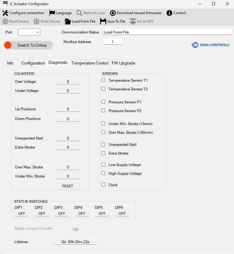
Diagnostic Tab
In this window, it is possible to view the status of the actuator and the occurrence of any anomalies:
-
Stroke [mm] shows the value of the actuator stroke calculated in mm during a calibration phase. It is a read-only value.
The COUNTERS section displays the number of events (mainly anomalies) that have occurred in the actuator. The events that can be logged are:
-
Over Voltage shows how many high supply voltage anomalies have occurred.
-
Under Voltage shows how many low supply voltage anomalies have occurred.
-
Up Positions: identifies the number of times that the actuator has been fully retracted.
-
Down Positions: identifies the number of times that the actuator has been fully extended.
-
Unexpected Stall: identifies an unexpected stall anomaly; this value represents the number of times that a stall has occurred within the stroke.
-
Extra Stroke: identifies an extra stroke anomaly; this value represents the number of times an extra stroke has occurred compared to the stroke calculated during the last calibration phase (out-of-range stroke).
-
Over Max. Stroke: shows how many stroke anomalies calculated by the actuator in the calibration phase (stroke greater than 60 mm) have occurred.
-
Under Min. Stroke: shows how many stroke anomalies calculated by the actuator in the calibration phase (stroke less than 5 mm) have occurred.
-
RESET: allows to reset all the counters (Over Voltage, Under Voltage, Up Positions, Down Positions, Unexpected Stall, Extra Stroke, Over Max. Voltage, Under Min. Voltage).
The ERRORS section shows the detectable actuator errors:
-
Temperature Sensor T1: the temperature sensor connected to the T1 terminal (supply temperature) has an anomaly (if temperature sensors are required for the enabled functions).
-
Temperature Sensor T2: the temperature sensor connected to the terminal indicated with T2 (return temperature) has an anomaly (if temperature sensors are required for the enabled functions).
-
Pressure Sensor P1: the pressure sensor connected to the A1 terminal (input pressure) has an anomaly.
-
Pressure Sensor P2: the pressure sensor connected to the A2 terminal (output pressure) has an anomaly.
-
Under Min. Stroke (<5mm): during the calibration phase, a stroke was calculated below the minimum allowed value.
-
Over Max. Stroke (>60mm): during the calibration phase, a stroke above the maximum allowed value was calculated.
-
Unexpected Stall: the actuator is in an unexpected stall condition in the stroke range.
-
Extra Stroke: the actuator is in an extra stroke condition; therefore, the actuator is in a position beyond the calculated stroke.
-
Low Supply Voltage: the power supply of the actuator is below the minimum allowed threshold (the performance of the actuator is not guaranteed).
-
High Supply Voltage: the power supply of the actuator is above the maximum allowed threshold (the performance of the actuator is not guaranteed).
-
Clock: indicates that the time and date have not been set in the actuator since the last time the actuator was switched on (it is necessary to enable the energy function and, consequently, to read the energy data). Synchronization is carried out in the Configuration tab, as described in the specific paragraph.
Active errors are highlighted in red color.
The STATUS SWITCHES section allows the user to read the DIP switches configuration set on the actuator. The status of the switches is updated only after having engaged and disengaged manual override or after a reset command or after having power off/on the actuator.
-
Status Jumper Failsafe: shows the jumper status (up or down) to indicate if the jumper on the emergency return board is inserted or not (it determines the fail-safe direction). The Status jumper Failsafe is applicable only if the Jumper is set on Enabled.
-
Lifetime: shows how long the actuator has been switched on.
The variables present in this window are read when the “Read Device” item is clicked from the dropdown menu
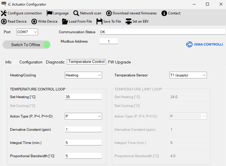
Temperature Control Tab
In this window, it is possible to configure and check the parameters of the temperature loop function.
This function is enabled only if the actuator is installed on a PICV (iC or custom) and both temperature sensors are correctly installed.
To save the set values, press the “Enter” key on the keyboard.
The 2 sections in this tab are enabled/disabled (gray color) based on the enabled function in the Configuration tab.
-
Heating/Cooling/Automatic (ΔT): sets a cooling or heating or automatic (based on ΔT) mode.
-
Temperature Sensor: sets the temperature sensor (T1 supply, T2 return, or ΔT) to use in the selected temperature function.
The TEMPERATURE CONTROL/LIMIT LOOP section allows the user to set the parameters for the temperature control/limitations functions:
-
Set [°C]: represents the temperature setpoint value.
-
Action Type (P, P+I, P+I+D) represents the type of control of the system to be used to regulate the desiderate temperature. To write the selected value into the actuator, press the Enter key on the keyboard.
-
Derivative Constant (gain): represents the contribution of the derivative action.
-
Integral Time (min): defines the time within which the proportional action is proposed again.
-
Proportional Bandwidth ∆T [°C]: represents the temperature error value (error = current temperature value - setpoint temperature), beyond which the valve will be fully open.
To save the desired value it is necessary to press the “Enter” key on the keyboard. To save all data, press “Write Device”.
Furthermore, it is possible to do an instantaneous read of the single information selected on the specific label.
Power Control Tab
In this window, it is possible to configure and check the parameters of the Power Control function.
To save the set value of design power and max power limit, press the Enter key on the keyboard.
The 2 sections in this tab are enabled/disabled (gray color) based on the enabled function in the Configuration tab
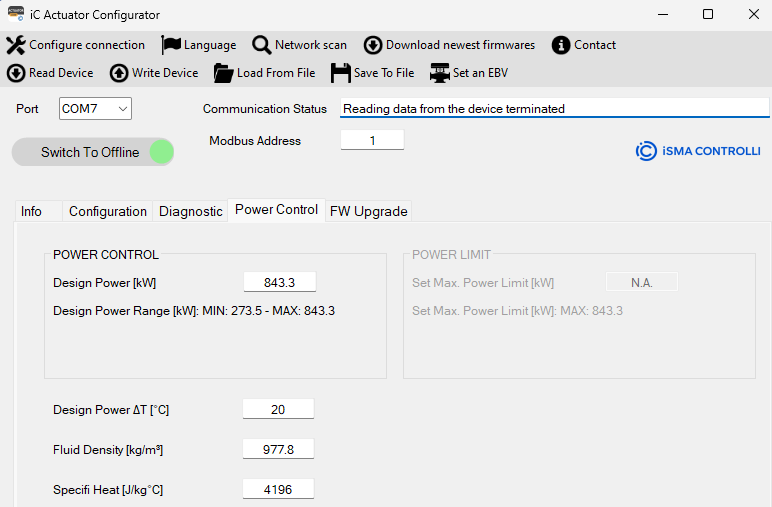
The POWER CONTROL section allows the user to set the information for the power control function, in particular:
-
Design power [kW] is the value of the power desired.
-
Design Power Range [kW]: it represents the maximum and the minimum value the Design Power can assume for the type of valves selected (for VLX6P it is 57.0-227.9);
The POWER LIMIT SECTION allows the user to set the information about the power limit value that the actuator can’t exceed.
in detail:
-
Design Power ∆T: it is the temperature used to define the Nominal Power of the valve.
-
Max. Power Limit [kW]: is the maximum power limit desired.
-
Max. Power Limit Range [kW]: it represents the maximum and the minimum value the Power can assume for the type of valve selected (for VLX6P, it is 57.0-227.9).
-
Fluid density [Kg/m3]: this value indicates the density of the fluid (default setting water 977.8 Kg/m3);
-
Specific Heat [J/Kg °C]: this value indicates the specific heat of the fluid (default setting water 4196 J/Kg °C).
Energy Tab
In this window, it is possible to read the parameters of the Energy function and read the monthly consumption as histograms.
To save the set values, press the “Enter” key on the keyboard.
This function is enabled only if the actuator is installed on a PICV (iC or custom), both temperature sensors are correctly installed, and the date and hour are synchronized.
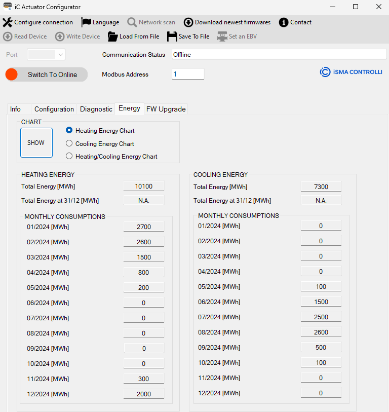
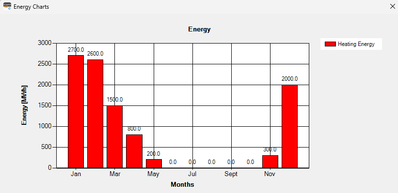
The CHART section allows the user to observe the histogram about the energy in the 12 months of the year regarding:
-
Heating Energy
-
Cooling Energy
-
Heating/Cooling Energy
The HEATING and COOLING ENERGY section shows:
-
Total Energy [MWh]: this value shows the total energy reading used until that moment.
-
Total Energy at 31/12/2023 [MWh]: this value shows the total energy reading at the end of the year.
-
MONTHLY CONSUMPTION [MWh]: in this section it is reported the energy heating/cooling consumption for each month. If for a month there are no registered values, or they haven’t been calculated yet, then it will appear N/A.
The variables present in this window are read by the actuator and displayed when the “Read Device” item is clicked from the drop-down menu.
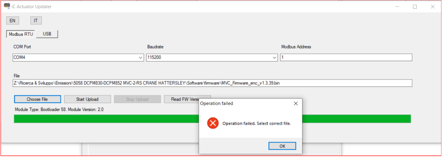
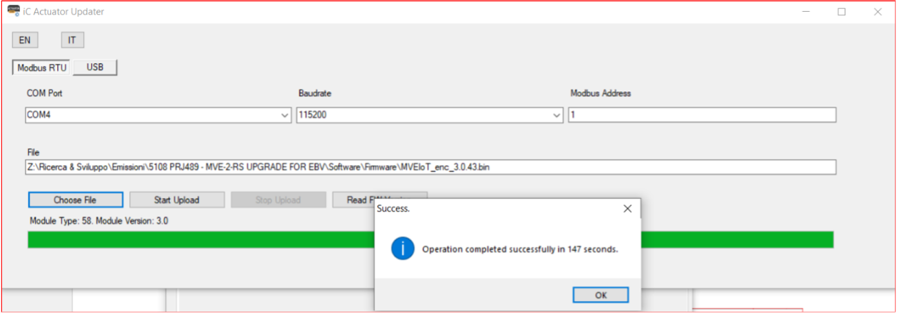
FW Upgrade Tab
After the selection of this tab, the following window is opened:
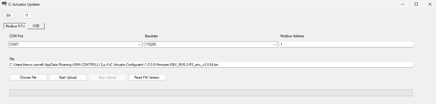
In this window, it is possible to upgrade the actuator's firmware using Modbus RTU protocol or USB.
This page is available in English and Italian.
To perform the firmware download, it is necessary:
-
Select the proper communication protocol (Modbus RTU or USB)
-
Select COM Port (in case of using Modbus protocol to download firmware)
-
Select the correct Baudrate (it should be the same used to communicate with the actuator).
-
Select Modbus Address (it should be the same used to communicate with the actuator).
-
Select the proper firmware file (with button “Choose File”).
-
Start the firmware download by pressing the Start Upload button.
-
Wait for a message about the result of operation (completed successfully or operation failed).
If the firmware is corrected, download the following window that appears.
In case of not correct file the following window appears.