Introduction
Setting up an AAC20 as a Modbus TCP slave involves configuring coil and register addresses correctly to ensure proper communication between devices. Misconfiguration can lead to unexpected behavior when reading or writing values.
Good Practice
When configuring the AAC20 for use with Modbus TCP, it is crucial to understand that the device uses a unified addressing range for all points, which includes both coils and holding registers. This setup can lead to confusion if not properly managed.
To correctly configure the device, follow these steps:
-
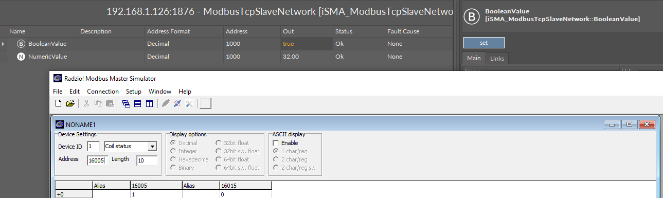
Unified Addressing: Recognize that if a holding register and a coil share the same decimal address, changes to the coil will affect the corresponding holding register. For example, if you set a coil at address 1000 decimal, 5th bit, and change this coil to true, the holding register at address 1000 will show a value of 32 (since 2^5 = 32).
-
Accessing Coils and Registers:
-
Coils can be accessed directly using their address and bit position. For instance, a coil set at address 1000 decimal, 5th bit, can be accessed using Modbus function codes 0x03 (Read Holding Registers) and 0x06 (Write Single Register) for its corresponding holding register bit.
-
Additionally, the same coil can be accessed at a calculated address using Modbus function codes 0x01 (Read Coils) and 0x05 (Write Single Coil). The address calculation is performed as follows:
Calculated Address = 16 * Original Address + Bit NumberFor the given example, the address would be
16 * 1000 + 5 = 16005.
-
-
Testing and Verification:
-
Use a Modbus client like Modscan32 to verify the configuration. Ensure you are accessing the correct addresses based on your requirements and the described addressing method.
-
Check both the direct coil/bit address and the calculated address to confirm that both pathways provide consistent and expected results.
-