The document outlines how to configure the iSMA-B-2D controller to work in the ON/OFF Control mode using the iSMA Configurator and the CFG DIP switch.
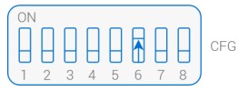
1. Set the 6th CFG DIP switch to on according to the figure below.

Figure 1. The ON/OFF Control mode CFG DIP switch configuration
2. Depending on the type of the light control switches connected to the device, set the 1st CFG DIP switch to:
-
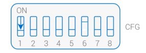
OFF if monostable switches are used;

Figure 2. CFG DIP switch configuration for monostable switches
-
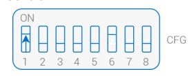
ON if bistable switches are used.

Figure 3. CFG DIP switch configuration for bistable switches
3. Depending on the number of connected switches and controlled zones, the 2nd and 4th CFG DIP switches have to be correctly configured. If both zones are to be controlled with two separate switches, 2nd and 4th CFG DIP switches have to set to off. In case one switch is to control both zones, set the CFG DIP switch as follows:
-
switch connected to the I1 input - 2nd CFG DIP switch to ON, 4th to OFF;
-
switch connected to the I2 input - 2nd CFG DIP switch to OFF, 4th to ON.
4. Similarly as in case of switches, controlling light with presence sensors (PIR) can be carried out with two separate sensors, or one sensor controlling both zones. Selection of the sensors configuration is performed by proper setting the 3rd and 5th CFG DIP switch. If both of them are in OFF position, two sensors controlling both zones individually have to be connected to S1 and S2 inputs. In case one sensor controls both zones, the CFG DIP switch is configured as follows:
-
sensor connected to S1 input - 3rd CFG DIP switch set to ON, 5th to OFF;
-
sensor connected to S2 input - 3rd CFG DIP switch set to OFF, 5th to ON.
The below figure depicts an example configuration of the CFG DIP switch in the iSMA-B-2D device for the ON/OFF Control mode. In this case, the PIR sensor is connected to the S1 input and controls both lighting zones, while monostable switches are connected to the I3 and I4 inputs and control two zones independently.

Figure 4. Example of the DIP switch configuration for the ON/OFF Control mode
5. Connect the iSMA-B-2D device to the PC using the micro USB cable or the USB-RS485 switch.
6. Open the iSMA Configurator and connect to the iSMA-B-2D device.
7. Go to the PIR Sensors tab to configure PIR sensors. In the PIR Sensors tab, in the PIR type slot, select the type of connected sensors:
-
normally open (NO),
-
normally closed (NC).
In the PIR Off Delay slot, configure the time, after which the light is switched off in case no human presence is detected in the room.
Having completed these steps, the iSMA-B-2D device is ready to work in the ON/OFF Control mode.
