The iSMA Configurator offers some specific features to manage the light level control mode in the iSMA-B-2D device. There are five specifically designed tabs to configure lighting, occupancy and lux sensors settings to enable proper operation of the LLC mechanism.
Lighting 1 and Lighting 2 Tabs
In the LLC mode both Lighting tabs work the same as in the DALI mode with 2 differences:
-
The Lighting mode field now reads the LLC mode if the iSMA-B-2D device is set to LLC;
-
Both Dimming State and Setpoint fields for separate ballasts are read-only.
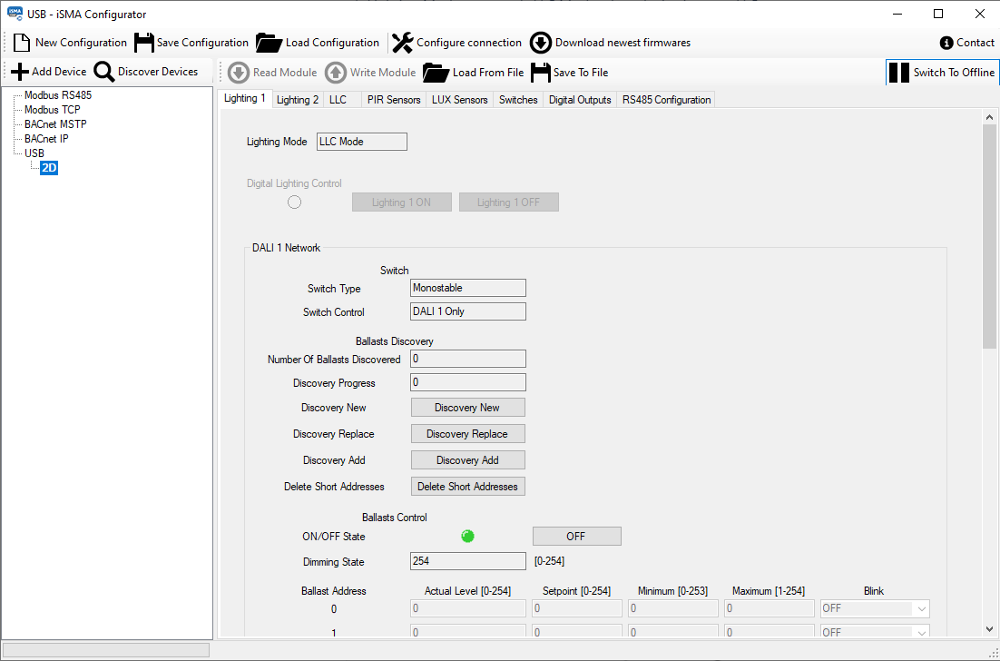
Lighting tabs 1 and 2 for devices working in the LLC mode
LLC Tab
The LLC tab includes fields to configure parameters of the light level control mode. Each of these parameters has a default value set for the automatic algorithm that normally operates the LLC mode; this specifically refers to the Kp, Ki, Kd, and Offset parameters, which configure the operation of the PID loop controlling the LLC algorithm.
-
LLC Zone Count: switches between 1 and 2 zones;
-
Setpoint (for each zone): sets the setpoint value for the light intensity;
-
Kp (for each zone): adjusts the proportional response of the PID controller;
-
Ki (for each zone): adjusts the integral response of the PID controller;
-
Kd (for each zone): adjusts the derivative response of the PID controller;
-
Offset (for zone 2): sets the output offset between DALI lines in single zone mode.
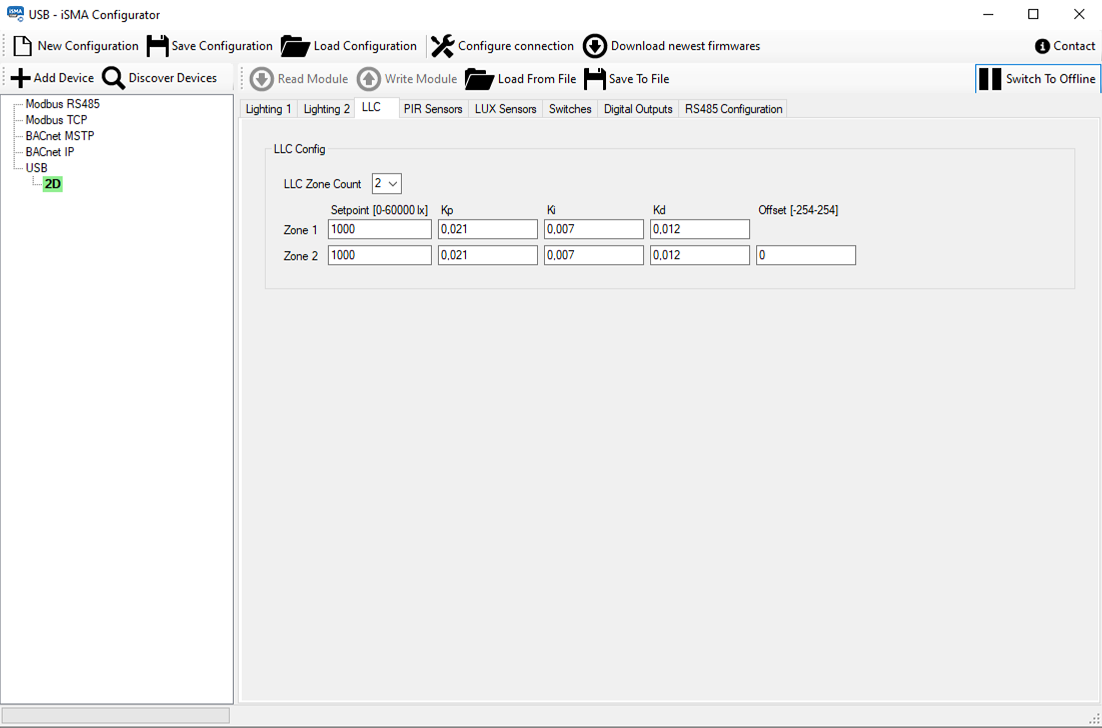
The LLC tab
PIR Sensors Tab
The PIR Sensors tab allows to set parameters for each sensor connected to digital inputs:
-
Input Name: displays inputs that PIR sensors should be connected to: if the LLC mode is enabled, the DI3, DI4 are displayed, in other modes DI1, DI2 are displayed;
-
Input State: displays a current physical state of the input;
-
Input Blocking: blocks or unblocks the input;
-
PIR Type: sets the input type (NC/NO);
-
Control Mode: displays the DALI line, which the sensor corresponds to;
-
PIR Off Delay: sets the time without PIR detection (counted from finished dimming), after which the light should be turned off;
-
PIR Dimm Time: sets the time without PIR detection, after which the light dims to the set level;
-
PIR Dimm Level: sets the proportional level to which the light should get dimmed;
-
PIR Status: displays the sensors statuses.
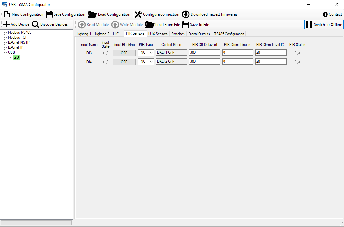
The PIR sensors tab
LUX Sensors Tab
New tab was added titled “LUX Sensors” for configuring lux sensors parameters with following fields:
-
Input Name: displays inputs that lux sensors should be connected to: S1, S2 for the LLC mode, ‘-‘ for both sensors otherwise;
-
Input value: displays the current state read from the input;
-
Sensor Type: sets the sensors type:
-
Available options: 0-10 V, 0-5 V, 2-10 V, 0-20 mA, 4-20 mA;
-
-
Enable: enables or disables individual sensors;
-
Min: sets the low limit of lux sensors read range;
-
Max: sets the high limit of lux sensors read range;
-
Lux: displays the lux value read from the sensor.
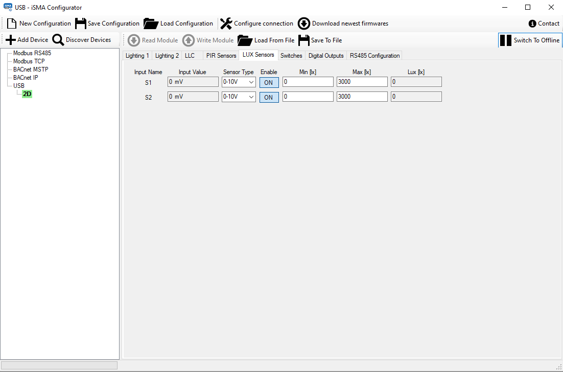
The LUX sensors tab