The list of Modbus registers is applicable for the following actuators family:
-
MVE-2-RS
-
MVC-2-RS
-
EBV
If the functionality does not apply to the selected actuator the connected register is not applicable.
The database is divided into the following sections:
-
Common Registers Section: It contains general information about the actuators.
-
Configuration Section: it contains the configuration registers area.
-
Diagnostic Section: it contains registers useful for diagnostics and error check.
-
Input/Output Section : it contains registers for command and feedback position.
-
Flow Rate Section: it contains registers for flow rate functions.
-
Setpoints Section: it contains registers for Temperature sensors setpoint.
-
Power Limit/Control Section: it contains registers for power control and limits loop.
-
Temperature Sensors Section: it contains registers for Temperature sensors reading.
-
Energy Heating/Cooling Section: it contains registers for the Energy function.
-
Clock Function Section: it contains registers for clock setting.
-
Output Loops Section: it contains registers for the main loop output value.
-
Power Section: it contains registers for the power function.
-
Loop Parameters Section: it contains registers for main loop parameters.
All registers and values are described in the following table:
|
Modbus Address |
Decimal Address |
Hex Address |
Register Name |
Access |
Description |
Persistence |
Group
|
|---|---|---|---|---|---|---|---|
|
40001 |
0 |
0x0 |
VERSION AND MODULE TYPE |
Read/write |
LSB – type (device ID), MSB - FW version / 10 |
YES |
Common registers |
|
30002 |
1 |
0x1 |
MODULE ADDRESS |
Read/write |
Modbus address setting via Modbus from 1 to 255 |
YES |
|
|
30004 |
3 |
0x3 |
COUNTER OF RECEIVED FRAMES (32-Bit) |
Read-only |
Default state is 0. Counting the received Modbus frames from the last powering up or module reset. |
NO |
|
|
30005 |
4 |
0x4 |
|||||
|
30006 |
5 |
0x5 |
COUNTER OF FRAMES WITH ERROR (32-Bit) |
Read-only |
Default state is 0. Counting the incorrect received Modbus frames from the last powering up or module reset. |
NO |
|
|
30007 |
6 |
0x6 |
|||||
|
30008 |
7 |
0x7 |
COUNTER OF SENT FRAMES (32-Bit) |
Read-only |
Default state is 0. Counting the sent Modbus frames from the last powering up or module reset. |
NO |
|
|
30009 |
8 |
0x8 |
|||||
|
30012 |
11 |
0xB |
UP TIME |
Read-only |
This 32-bit register contains module counting time in seconds from the last powering up or module reset |
NO |
|
|
30013 |
12 |
0xC |
|||||
|
30014 |
13 |
0xD |
SOURCE OF LAST DEVICE RESET |
Read-only |
Select the source of the last reset
|
YES |
|
|
40134 |
133 |
0x85 |
BACNET_DEVICEID |
Read/write |
Device BACnet ID |
YES |
|
|
40135 |
134 |
0x86 |
|||||
|
40136 |
135 |
0x87 |
BAUD RATE |
Read/write |
Transmission speed is defined by the user calculated using the formula: baud rate = register value x 10. The default value is 115200 bps. |
YES |
|
|
40137 |
136 |
0x88 |
STOP Bits |
Read/write |
Supported values are 1 and 2. The default value is 1. |
YES |
|
|
40138 |
137 |
0x89 |
DATA Bits |
Read/write |
Supported value is only 8. |
YES |
|
|
40139 |
138 |
0x8A |
PARITY Bit |
Read/write |
Parity bit. The default value is 0 (no parity). Allowed values: 0 (default): none, 1: odd, 2: even |
YES |
|
|
40140 |
139 |
0x8B |
RESPONSE DELAY |
Read/write |
Delay in ms before sending the response. The default value is 0. |
YES |
|
|
30190 |
190 |
0xBE |
- |
Read-only |
Auxiliary register (used for detecting first device activation, 0x5555=device activated) |
YES |
|
|
30301 |
300 |
0x12C |
DEVICE VERSION DESIGNATION |
Read-only |
Select the device version designation
|
YES |
Configuration |
|
30302 |
301 |
0x12D |
HARDWARE VERSION |
Read-only |
Hardware version |
YES |
|
|
30303 |
302 |
0x12E |
BOOTLOADER VERSION |
Read-only |
Bootloader version |
YES |
|
|
30304 |
303 |
0x12F |
FIRMWARE VERSION |
Read-only |
Firmware version |
YES |
|
|
30305 |
304 |
0x130 |
SERIAL NUMBER 1 |
Read-only |
It’s configured in production |
YES |
|
|
30306 |
305 |
0x131 |
SERIAL NUMBER 2 |
Read-only |
It’s configured in production |
YES |
|
|
30307 |
306 |
0x132 |
SERIAL NUMBER 3 |
Read-only |
It’s configured in production |
YES |
|
|
30308 |
307 |
0x133 |
SERIAL NUMBER 4 |
Read-only |
It’s configured in production |
YES |
|
|
41005 |
1004 |
0x3EC |
MAXIMUM FLOW SETTING |
Read/write |
Select the caliber position:
|
YES |
|
|
41006 |
1005 |
0x3ED |
TYPE OF CONTROL |
Read/write |
Select the actuator type of control:
|
YES |
|
|
41007 |
1006 |
0x3EE |
DIRECT/REVERSE & FAILSAFE DIRECTION SETTING |
Read/write |
Select the actuator's action (direct or reverse) and fail-safe direction:
|
YES |
|
|
41008 |
1007 |
0x3EF |
FORCE CALIBRATION |
Read/write |
Force calibration (valve stroke learning); 1 - force calibration (automatic reset of value after calibration) |
NO |
|
|
41009 |
1008 |
0x3F0 |
JUMPER ENABLE (ER board) |
Read/write |
Fail-safe jumper enable setting: 0 (default) - jumper enabled, 1 - jumper disabled
|
YES |
|
|
41010 |
1009 |
0x3F1 |
CHANGEOVER SETTING |
Read/write |
Temperature loops action selection:
|
YES |
|
|
41011 |
1010 |
0x3F2 |
TEMPERATURE PROBE SELECTION |
Read/write |
Temperature probe selection:
|
YES |
|
|
41013 |
1012 |
0x3F4 |
VALVE CHARACTERISTIC CONFIGURATION |
Read/write |
Select type of movement of the valve: Linear-0, EQP-1 |
YES |
|
|
41014 |
1013 |
0x3F5 |
FUNCTIONS ENABLE |
Read/write |
Actuator function setting (bit0 = 1-BMS - default):
|
YES |
|
|
31015 |
1014 |
0x3F6 |
FUNCTIONS STATUS |
Read-only |
Actuator function setting:
|
NO |
|
|
41016 |
1015 |
0x3F7 |
% MINIMUM OPENING VALVE |
Read/write |
Set minimum opening valve when the temperature loops and limits are active. |
YES |
|
|
31017 |
1016 |
0x3F8 |
DIP SWITCH & PUSH BUTTON & JUMPER STATUS |
Read-only |
DIP switches and jumper status:
Bit 4: DIP5 status: “No action” (OFF), “Set and EBV” (ON)
|
NO |
|
|
41018 |
1017 |
0x3F9 |
VALVE TYPE |
Read/write |
Select valve model
|
YES |
|
|
41019 |
1018 |
0x3FA |
VALVE STROKE (mm*100) |
Read/write |
Valve stroke (mm*100) - after calibration phase |
YES |
|
|
41020 |
1019 |
0x3FB |
OVERVOLTAGE EVENTS (24 V AC > 20%) (230 V > 10%) |
Read/write |
Overvoltage events (24 V AC > 20%) (230 V > 20%) |
YES |
Diagnostic |
|
41021 |
1020 |
0x3FC |
UNDERVOLTAGE EVENTS (V AC < 20%) (230 V < 10%) |
Read/write |
Undervoltage events (V AC < 20%) (230 V < 20%) |
YES |
|
|
41022 |
1021 |
0x3FD |
FULLY OPEN EVENTS |
Read/write |
Fully opened events |
YES |
|
|
41023 |
1022 |
0x3FE |
FULLY CLOSE EVENTS |
Read/write |
Fully closes events |
YES |
|
|
41024 |
1023 |
0x3FF |
UNEXPECTED STALL CONDITION EVENTS (within calculated stroke) |
Read/write |
Unexpected stall condition events (within calculated stroke) |
YES |
|
|
41025 |
1024 |
0x400 |
UNEXPECTED STALL CONDITION EVENTS (outside calculated stroke) |
Read/write |
Unexpected stall condition events (outside calculated stroke) |
YES |
|
|
41026 |
1025 |
0x401 |
VALVE STROKE ERROR > max. (60 mm for EMV/MVE-2-RS and 12mm for MVC-2-RS) |
Read/write |
Valve stroke error > max. (60 mm for EMV/MVE-2-RS and 12mm for MVC-2-RS)) |
YES |
|
|
41027 |
1026 |
0x402 |
VALVE STROKE ERROR < min. (5 mm for EMV/MVE-2-RS and 2mm for MVC-2-RS) |
Read/write |
Valve stroke error < min. (5 mm for EMV/MVE-2-RS and 12mm for MVC-2-RS)) |
YES |
|
|
31028 |
1027 |
0x403 |
ACTUATOR OPERATING MODE |
Read-only |
Actuator operating mode (0 - not active) (1- active):
|
NO |
|
|
31029 |
1028 |
0x404 |
ERROR TYPE |
Read-only |
Error type: (0- no error) (1- error):
|
YES |
|
|
41034 |
1033 |
0x409 |
ACTUATOR RESET |
Read/write |
Force actuator reset (1) |
NO |
Configuration |
|
41035 |
1034 |
0x40A |
BMS COMMAND |
Read/write |
BMS command (0-100%) *10 |
NO |
Input/ Output |
|
31038 |
1037 |
0x40D |
FEEDBACK |
Read-only |
Valve position (0-100%) *10 |
NO |
|
|
41044 |
1043 |
0x413 |
MAX FLOW RATE |
Read/write |
Select Nominal flow rate (m3/h)
EBV (m3/h):
MVC-2-RS (l/h):
|
YES |
Flow rate |
|
41045 |
1044 |
0x414 |
DESIGN FLOW RATE |
Read/write |
Design flow rate must be between ¼ of Qnom and Qnom (*10) |
YES |
|
|
31047 |
1046 |
0x416 |
INPUT PRESSURE (P1) |
Read-only |
Input pressure value (bar*100) |
NO |
|
|
31048 |
1047 |
0x417 |
OUTPUT PRESSURE (P2) |
Read-only |
Output pressure value (bar*100) |
NO |
|
|
31049 |
1048 |
0x418 |
DIFFERENTIAL PRESSURE |
Read-only |
∆P value (P1 – P2) (bar*100) |
NO |
|
|
41080 |
1079 |
0x437 |
FLOW RATE SP X1 |
Read/write |
Flow rate X1 (custom valve)*10 |
YES |
|
|
41081 |
1080 |
0x438 |
VALVE POSITION Y1 |
Read/write |
Valve Position Y1 (custom valve)*10 |
YES |
|
|
41082 |
1081 |
0x439 |
FLOW RATE SP X2 |
Read/write |
Flow rate X2 (custom valve)*10 |
YES |
|
|
41083 |
1082 |
0x43A |
VALVE POSITION Y2 |
Read/write |
Valve position Y2 (custom valve)*10 |
YES |
|
|
41084 |
1083 |
0x43B |
FLOW RATE SP X3 |
Read/write |
Flow rate X3 (custom valve)*10 |
YES |
|
|
41085 |
1084 |
0x43C |
VALVE POSITION Y3 |
Read/write |
Valve position Y3 (custom valve)*10 |
YES |
|
|
41086 |
1085 |
0x43D |
FLOW RATE SP X4 |
Read/write |
Flow rate X4 (custom valve)*10 |
YES |
|
|
41087 |
1086 |
0x43E |
VALVE POSITION Y4 |
Read/write |
Valve position Y4 (custom valve)*10 |
YES |
|
|
41088 |
1087 |
0x43F |
FLOW RATE SP X5 |
Read/write |
Flow rate X5 (custom valve)*10 |
YES |
|
|
41089 |
1088 |
0x440 |
VALVE POSITION Y5 |
Read/write |
Valve position Y5 (custom valve)*10 |
YES |
|
|
41090 |
1089 |
0x441 |
FLOW RATE SP X6 |
Read/write |
Flow rate X6 (custom valve)*10 |
YES |
|
|
41091 |
1090 |
0x442 |
VALVE POSITION Y6 |
Read/write |
Valve position Y6 (custom valve)*10 |
YES |
|
|
41092 |
1091 |
0x443 |
FLOW RATE SP X7 |
Read/write |
Flow rate X7 (custom valve)*10 |
YES |
|
|
41093 |
1092 |
0x444 |
VALVE POSITION Y7 |
Read/write |
Valve position Y7 (custom valve)*10 |
YES |
|
|
41094 |
1093 |
0x445 |
FLOW RATE SP X8 |
Read/write |
Flow rate X8 (custom valve)*10 |
YES |
|
|
41095 |
1094 |
0x446 |
VALVE POSITION Y8 |
Read/write |
Valve position Y8 (custom valve)*10 |
YES |
|
|
41096 |
1095 |
0x447 |
FLOW RATE SP X9 |
Read/write |
Flow rate X9 (custom valve)*10 |
YES |
|
|
41097 |
1096 |
0x448 |
VALVE POSITION Y9 |
Read/write |
Valve position Y9 (custom valve)*10 |
YES |
|
|
41098 |
1097 |
0x449 |
FLOW RATE SP X10 |
Read/write |
Flow rate X10 (custom valve)*10 |
YES |
|
|
41099 |
1098 |
0x44A |
VALVE POSITION Y10 |
Read/write |
Valve position Y10 (custom valve)*10 |
YES |
|
|
31100 |
1099 |
0x44B |
INDICATED FLOW RATE |
Read-only |
Calculated flow rate (m3/h)*100 (for EBV/MVE-2-RS) and l/h (MVC-2-RS) |
NO |
|
|
41101 |
1100 |
0x44C |
SETPOINT ∆T CONTROL HEATING |
Read/write |
Set heating ∆T control (°C*10) |
YES |
Setpoints |
|
41102 |
1101 |
0x44D |
SETPOINT ∆T CONTROL COOLING |
Read/write |
Set cooling ∆T control (°C*10) |
YES |
|
|
41103 |
1102 |
0x44E |
SETPOINT SUPPLY TEMPERATURE CONTROL HEATING |
Read/write |
Set heating supply temperature (°C*10) |
YES |
|
|
41104 |
1103 |
0x44F |
SETPOINT SUPPLY TEMPERATURE CONTROL COOLING |
Read/write |
Set cooling supply temperature (°C*10) |
YES |
|
|
41105 |
1104 |
0x450 |
SETPOINT RETURN TEMPERATURE CONTROL HEATING |
Read/write |
Set heating return temperature (°C*10) |
YES |
|
|
41106 |
1105 |
0x451 |
SETPOINT RETURN TEMPERATURE CONTROL COOLING |
Read/write |
Set cooling return temperature (°C*10) |
YES |
|
|
41107 |
1106 |
0x452 |
SETPOINT MINIMUM ∆T HEATING |
Read/write |
Set heating ∆T limitation (°C*10) |
YES |
|
|
41108 |
1107 |
0x453 |
SETPOINT MINIMUM ∆T COOLING |
Read/write |
Set cooling ∆T limitation (°C*10) |
YES |
|
|
41109 |
1108 |
0x454 |
SETPOINT MAX. SUPPLY TEMPERATURE HEATING |
Read/write |
Set heating supply temperature limit (°C*10) |
YES |
|
|
41110 |
1109 |
0x455 |
SETPOINT MIN. SUPPLY TEMPERATURE COOLING |
Read/write |
Set cooling supply temperature limit (°C*10) |
YES |
|
|
41111 |
1110 |
0x456 |
SETPOINT MAX. RETURN TEMPERATURE HEATING |
Read/write |
Set heating return temperature limit (°C*10) |
YES |
|
|
41112 |
1111 |
0x457 |
SETPOINT MIN. RETURN TEMPERATURE COOLING |
Read/write |
Set cooling return temperature limit (°C*10) |
YES |
|
|
41113 |
1112 |
0x458 |
DESIGN POWER |
Read/write |
Set maximum power (control) (kW*10) |
YES |
Power control/limit |
|
41114 |
1113 |
0x459 |
SET MAX. POWER LIMIT |
Read/write |
Set max power (limit) (kW*10) |
YES |
|
|
31115 |
1114 |
0x45A |
SUPPLY TEMPERATURE VALUE |
Read-only |
Supply temperature value (°C*10) |
NO |
Temperature Sensors |
|
31116 |
1115 |
0x45B |
RETURN TEMPERATURE VALUE |
Read-only |
Return temperature value (°C*10) |
NO |
|
|
31117 |
1116 |
0x45C |
∆T VALUE (S1 – S2) |
Read-only |
∆T value (T1 – T2) (°C*10) |
NO |
|
|
31120 |
1119 |
0x45F |
INSTANT POWER |
Read-only |
Instant power (kW*10) |
YES |
Energy Heating/Cooling |
|
31121 |
1120 |
0x460 |
HEATING ENERGY LSR |
Read-only |
Total heating energy (kWh*10) less significant word |
YES |
|
|
31122 |
1121 |
0x461 |
HEATING ENERGY MSR |
Read-only |
Total heating energy (kWh*10) more significant word |
YES |
|
|
31123 |
1122 |
0x462 |
COOLING ENERGY LSR |
Read-only |
Total cooling energy (kWh*10) less significant word |
YES |
|
|
31124 |
1123 |
0x463 |
COOLING ENERGY MSR |
Read-only |
Total cooling energy (kWh*10) more significant word |
YES |
|
|
31139 |
1138 |
0x472 |
HEATING ENERGY AT 31/12 LSR |
Read-only |
Energy (Heating) at the end of the year (kWh*10) less significant word |
YES |
|
|
31140 |
1139 |
0x473 |
HEATING ENERGY AT 31/12 MSR |
Read-only |
Energy (Heating) at the end of the year (kWh*10) more significant word |
YES |
|
|
31141 |
1140 |
0x474 |
HEATING ENERGY AT VALUE 1 |
Read-only |
Energy (Heating) value 1 (MWh*10) |
YES |
|
|
31142 |
1141 |
0x475 |
HEATING ENERGY AT VALUE 2 |
Read-only |
Energy (Heating) value 2 (MWh*10) |
YES |
|
|
31143 |
1142 |
0x476 |
HEATING ENERGY AT VALUE 3 |
Read-only |
Energy (Heating) value 3 (MWh*10) |
YES |
|
|
31144 |
1143 |
0x477 |
HEATING ENERGY AT VALUE 4 |
Read-only |
Energy (Heating) value 4 (MWh*10) |
YES |
|
|
31145 |
1144 |
0x478 |
HEATING ENERGY AT VALUE 5 |
Read-only |
Energy (Heating) value 5 (MWh*10) |
YES |
|
|
31146 |
1145 |
0x479 |
HEATING ENERGY AT VALUE 6 |
Read-only |
Energy (Heating) value 6 (MWh*10) |
YES |
|
|
31147 |
1146 |
0x47A |
HEATING ENERGY AT VALUE 7 |
Read-only |
Energy (Heating) value 7 (MWh*10) |
YES |
|
|
31148 |
1147 |
0x47B |
HEATING ENERGY AT VALUE 8 |
Read-only |
Energy (Heating) value 8 (MWh*10) |
YES |
|
|
31149 |
1148 |
0x47C |
HEATING ENERGY AT VALUE 9 |
Read-only |
Energy (Heating) value 9 (MWh*10) |
YES |
|
|
31150 |
1149 |
0x47D |
HEATING ENERGY AT VALUE 10 |
Read-only |
Energy (Heating) value 10 (MWh*10) |
YES |
|
|
31151 |
1150 |
0x47E |
HEATING ENERGY AT VALUE 11 |
Read-only |
Energy (Heating) value 11 (MWh*10) |
YES |
|
|
31152 |
1151 |
0x47F |
HEATING ENERGY AT VALUE 12 |
Read-only |
Energy (Heating) value 12 (MWh*10) |
YES |
|
|
31153 |
1152 |
0x480 |
COOLING ENERGY AT 31/12 LSR |
Read-only |
Energy (Cooling) at the end of the year (kWh*10) |
YES |
|
|
31154 |
1153 |
0x481 |
COOLING ENERGY AT 31/12 MSR |
Read-only |
YES |
|
|
|
31155 |
1154 |
0x482 |
COOLING ENERGY VALUE 1 |
Read-only |
Energy (Cooling) value 1 (MWh*10) |
YES |
|
|
31156 |
1155 |
0x483 |
COOLING ENERGY VALUE 2 |
Read-only |
Energy (Cooling) value 2 (MWh*10) |
YES |
|
|
31157 |
1156 |
0x484 |
COOLING ENERGY VALUE 3 |
Read-only |
Energy (Cooling) value 3 (MWh*10) |
YES |
|
|
31158 |
1157 |
0x485 |
COOLING ENERGY VALUE 4 |
Read-only |
Energy (Cooling) value 4 (MWh*10) |
YES |
|
|
31159 |
1158 |
0x486 |
COOLING ENERGY VALUE 5 |
Read-only |
Energy (Cooling) value 5 (MWh*10) |
YES |
|
|
31160 |
1159 |
0x487 |
COOLING ENERGY VALUE 6 |
Read-only |
Energy (Cooling) value 6 (MWh*10) |
YES |
|
|
31161 |
1160 |
0x488 |
COOLING ENERGY VALUE 7 |
Read-only |
Energy (Cooling) value 7 (MWh*10) |
YES |
|
|
31162 |
1161 |
0x489 |
COOLING ENERGY VALUE 8 |
Read-only |
Energy (Cooling) value 8 (MWh*10) |
YES |
|
|
31163 |
1162 |
0x48A |
COOLING ENERGY VALUE 9 |
Read-only |
Energy (Cooling) value 9 (MWh*10) |
YES |
|
|
31164 |
1163 |
0x48B |
COOLING ENERGY VALUE 10 |
Read-only |
Energy (Cooling) value 10 (MWh*10) |
YES |
|
|
31165 |
1164 |
0x48C |
COOLING ENERGY VALUE 11 |
Read-only |
Energy (Cooling) value 11 (MWh*10) |
YES |
|
|
31166 |
1165 |
0x48D |
COOLING ENERGY VALUE 12 |
Read-only |
Energy (Cooling) value 12 (MWh*10) |
YES |
|
|
41182 |
1181 |
0x49D |
CLOCK MINUTES |
Read/write |
Clock minutes |
YES |
Clock function |
|
41183 |
1182 |
0x49E |
CLOCK HOURS |
Read/write |
Clock hours |
YES |
|
|
41184 |
1183 |
0x49F |
CLOCK DAY |
Read/write |
Clock day |
YES |
|
|
41185 |
1184 |
0x4A0 |
CLOCK MONTH |
Read/write |
Clock month |
YES |
|
|
41186 |
1185 |
0x4A1 |
CLOCK YEAR |
Read/write |
Clock year |
YES |
|
|
41187 |
1186 |
0x4A2 |
RESTORE FACTORY SETTING |
Read/write |
Set 1 to load default setting to the device and to EEPROM MEMORY |
NO |
Configuration |
|
41188 |
1187 |
0x4A3 |
FORCE FULLY CLOSE |
Read/write |
Allow to fully close the valve (overwrites the output from any function/loop) |
NO |
|
|
41189 |
1188 |
0x4A4 |
FORCE FULLY OPEN |
Read/write |
Allow to fully open the valve (overwrites the output from any function/loop) |
NO |
|
|
41190 |
1189 |
0x4A5 |
TEMPERATURE TEST MODE |
Read/write |
Set to 1, it’s possible to write the desired temperature value into supply and return temperature register (addr. 1114 and 1115). The values will not be read from temperature sensors. |
NO |
|
|
31192 |
1191 |
0x4A7 |
OUT LOOP ∆P |
Read-only |
Output loop ∆P (*10) |
NO |
Loop outputs |
|
31193 |
1192 |
0x4A8 |
OUT LOOP BMS |
Read-only |
Output loop BMS (*10) |
NO |
|
|
31194 |
1193 |
0x4A9 |
OUT LOOP FLOW RATE CONTROL |
Read-only |
Output loop flow rate control (*10) |
NO |
|
|
31196 |
1195 |
0x4AB |
OUT LOOP POWER |
Read-only |
Output loop power (*10) |
NO |
|
|
31197 |
1196 |
0x4AC |
OUT LOOP POWER LIMIT |
Read-only |
Output loop power limit (*10) |
NO |
|
|
31198 |
1197 |
0x4D |
OUT LOOP T CONTROL |
Read-only |
Output loop T control (*10) |
NO |
|
|
31199 |
1198 |
0x4AE |
OUT LOOP T LIMITS |
Read-only |
Output loop T limits (*10) |
NO |
|
|
31200 |
1199 |
0x4AF |
OUT LOOP "ACTIVE" |
Read-only |
Output loop "active" (*10) |
NO |
|
|
41207 |
1206 |
0x4B6 |
MAX. POWER |
Read/write |
Valve nominal power (kW)*10 |
YES |
Power |
|
41208 |
1207 |
0x4B7 |
MEDIA DENSITY |
Read/write |
Media density (*10): default value is for water at 20°C (Kg/m3) |
YES |
|
|
41209 |
1208 |
0x4B8 |
MEDIA SPECIFIC HEAT |
Read/write |
Media specific heat (*10): default value is for water (J/Kg°C) |
YES |
|
|
31213 |
1212 |
0x4BC |
CUSTOM NOMINAL POWER ΔT 20K |
Read-only |
Valve nominal power at 20°C (kW) (max.val) |
YES |
|
|
41231 |
1230 |
0x4CE |
LOOP TYPE P, P+I, P+I+D |
Read/write |
Loop type P, P+I, P+I+D |
YES |
Loop parameters |
|
41232 |
1231 |
0x4CF |
DERIVATIVE TIME (gain) |
Read/write |
Derivative time (gain) |
YES |
|
|
41233 |
1232 |
0x4D0 |
INTEGRAL TIME (min.) |
Read/write |
Integral time (min.) |
YES |
|
|
41234 |
1233 |
0x4D1 |
PROPORTIONAL BANDWIDTH ∆T (°C*10) |
Read/write |
Proportional bandwidth ∆T (°C*10) |
YES |
|
|
31241 |
1240 |
0x4D8 |
MONTH TIMESTAMP OF 31ST DECEMBER |
Read-only |
Month timestamp for energy at 31st December |
YES |
|
|
31242 |
1241 |
0x4D9 |
YEAR TIMESTAMP OF 31ST DECEMBER |
Read-only |
Year timestamp for energy at 31st December |
YES |
|
|
31243 |
1242 |
0x4DA |
MONTH TIMESTAMP OF VALUE 1 |
Read-only |
Month timestamp for value 1 |
YES |
|
|
31244 |
1243 |
0x4DB |
YEAR TIMESTAMP OF VALUE 1 |
Read-only |
Year timestamp for value 1 |
YES |
|
|
31245 |
1244 |
0x4DC |
MONTH TIMESTAMP OF VALUE 2 |
Read-only |
Month timestamp for value 2 |
YES |
|
|
31246 |
1245 |
0x4DD |
YEAR TIMESTAMP OF VALUE 2 |
Read-only |
Year timestamp for value 2 |
YES |
|
|
31247 |
1246 |
0x4DE |
MONTH TIMESTAMP OF VALUE 3 |
Read-only |
Month timestamp for value 3 |
YES |
|
|
31248 |
1247 |
0x4DF |
YEAR TIMESTAMP OF VALUE 3 |
Read-only |
Year timestamp for value 3 |
YES |
|
|
31249 |
1248 |
0x4E0 |
MONTH TIMESTAMP OF VALUE 4 |
Read-only |
Month timestamp for value 4 |
YES |
|
|
31250 |
1249 |
0x4E1 |
YEAR TIMESTAMP OF VALUE 4 |
Read-only |
Year timestamp for value 4 |
YES |
|
|
31251 |
1250 |
0x4E2 |
MONTH TIMESTAMP OF VALUE 5 |
Read-only |
Month timestamp for value 5 |
YES |
|
|
31252 |
1251 |
0x4E3 |
YEAR TIMESTAMP OF VALUE 5 |
Read-only |
Year timestamp for value 5 |
YES |
|
|
31253 |
1252 |
0x4E4 |
MONTH TIMESTAMP OF VALUE 6 |
Read-only |
Month timestamp for value 6 |
YES |
|
|
31254 |
1253 |
0x4E5 |
YEAR TIMESTAMP OF VALUE 6 |
Read-only |
Month timestamp for value 6 |
YES |
|
|
31255 |
1254 |
0x4E6 |
MONTH TIMESTAMP OF VALUE 7 |
Read-only |
Year timestamp for value 7 |
YES |
|
|
31256 |
1255 |
0x4E7 |
YEAR TIMESTAMP OF VALUE 7 |
Read-only |
Month timestamp for value 7 |
YES |
|
|
31257 |
1256 |
0x4E8 |
MONTH TIMESTAMP OF VALUE 8 |
Read-only |
Year timestamp for value 8 |
YES |
|
|
31258 |
1257 |
0x4E9 |
YEAR TIMESTAMP OF VALUE 8 |
Read-only |
Month timestamp for value 8 |
YES |
|
|
31259 |
1258 |
0x4EA |
MONTH TIMESTAMP OF VALUE 9 |
Read-only |
Year timestamp for value 9 |
YES |
|
|
31260 |
1259 |
0x4EB |
YEAR TIMESTAMP OF VALUE 9 |
Read-only |
Month timestamp for value 9 |
YES |
|
|
31261 |
1260 |
0x4EC |
MONTH TIMESTAMP OF VALUE 10 |
Read-only |
Year timestamp for value 10 |
YES |
|
|
31262 |
1261 |
0x4ED |
YEAR TIMESTAMP OF VALUE 10 |
Read-only |
Month timestamp for value 10 |
YES |
|
|
31263 |
1262 |
0x4EE |
MONTH TIMESTAMP OF VALUE 11 |
Read-only |
Year timestamp for value 11 |
YES |
|
|
31264 |
1263 |
0x4EF |
YEAR TIMESTAMP OF VALUE 11 |
Read-only |
Month timestamp for value 11 |
YES |
|
|
31265 |
1264 |
0x4F0 |
MONTH TIMESTAMP OF VALUE 12 |
Read-only |
Year timestamp for value 12 |
YES |
|
|
31266 |
1265 |
0x4F1 |
YEAR TIMESTAMP OF VALUE 12 |
Read-only |
Month timestamp for value 12 |
YES |
Common Registers Section
Version and module type
This register shows the firmware version (Most Significant Byte) and the device ID of the actuator (Least Significant Byte).
Modbus register: 40001
Module Address
Defines the Modbus address of the device from 1 to 255.
Modbus register: 30002
BACnet object: Network port, object ID: 0, properties: MAC address.
Counter of Received Frames (LSW)
This register contains the least significant word of the counter of received frames from the last powering-up or module reset.
Modbus register: 30004
Counter of Received Frames (MSW)
This register contains the most significant word of the counter of received frames from the last powering-up or module reset.
Modbus register: 30005
Counter of Frames with Error (LSW)
This register contains the least significant word of the counter of frames with error from the last powering-up or module reset.
Modbus register: 30006
Counter of Frames with Error (MSW)
This register contains the most significant word of the counter of frames with error from the last powering-up or module reset.
Modbus register: 30007
Counter of Sent Frames (LSW)
This register contains the least significant word of the counter of sent frames from the last powering-up or module reset.
Modbus register: 30008
Counter of Sent Frames (MSW)
This register contains the most significant word of the counter of sent frames from the last powering-up or module reset.
Modbus register: 30009
Up Time (LSW)
This register contains the least significant word of the uptime counter from the last powering-up or module reset.
Modbus register: 30012
BACnet object: type Analog value, object ID: 0, properties: Present value.
Up Time (MSW)
This register contains the most significant word of the uptime counter from the last powering-up or module reset.
Modbus register: 30013
BACnet object: type Analog value, object ID: 0, properties: Present value.
Source of last device reset
Source of last device reset
This register shows the source of the last reset, according to the table below:
|
Addr. value |
Source of the reset |
|---|---|
|
1 |
Power-on reset (POR) |
|
2 |
Brown-out detector (BOD12) |
|
4 |
Brown-out detector (BOD33) |
|
16 |
Ext. reset (EXT) |
|
32 |
Watchdog (WDT) |
|
64 |
System reset (SYST) |
Selection for source of the last reset
Modbus register: 30014
BACnet device ID
This register contains the least important two bytes of the BACnet ID value.
Modbus register: 40134
BACnet Device ID
This register contains the most important two bytes of the BACnet ID value.
Modbus register: 40135
Baud Rate
It defines the possibility to set the modbus protocol baud rate according to the following possibilities:
|
Addr. 1 (value) |
Modbus baud rate |
|---|---|
|
1 |
960 |
|
2 |
1920 |
|
3 |
3840 |
|
4 |
5760 |
|
5 |
7680 |
|
6 |
11520 (default) |
Selection of the Baud rate
Modbus register: 40136
BACnet object: Network port, object ID: 0, properties: link speed.
Stop Bits
Defines the number of stop bits in the Modbus communication parameters according to the following possibilities:
|
Addr. 136 (value) |
Number of stop bits |
|---|---|
|
1 |
1 |
|
2 |
2 |
Stop bits configuration for Modbus communication
Modbus register: 40137
Data Bits
Defines the number of stop bits in the Modbus communication parameters according to the following possibilities:
|
Addr.137 (value) |
Data bits |
|---|---|
|
8 |
Data has 8 bits |
Data bits configuration for Modbus communication
Parity Bit
Defines the value of parity bit in the Modbus communication parameters according to the following possibilities:
|
Addr.138 (value) |
Parity bit |
|---|---|
|
0 |
None |
|
1 |
Odd |
|
2 |
Even |
Parity bit configuration for Modbus communication
Modbus register: 40139
Response delay
This register shows the delay (in ms) before sending the response to the master. The default value is 0.
Modbus register: 40140
Auxiliary register
This auxiliary register is used for detecting the first device activation, 0x5555=device activated (it’s a read-only register).
Modbus register: 30190
Configuration Section
Device version designation
Defines the device version according to the table below (for MVE-2-RS):
|
Bit number |
Device description |
|
|---|---|---|
|
Addr. value |
Model |
|
|
1
|
129 |
MVE504-2-RS |
|
131 |
MVE506-2-RS |
|
|
133 |
MVE510-2-RS |
|
|
135 |
MVE515-2-RS |
|
|
137 |
MVE522-2-RS |
|
|
139 |
MVE204-2-RS |
|
|
141 |
MVE206-2-RS |
|
|
143 |
MVE210-2-RS |
|
|
145 |
MVE215-2-RS |
|
|
147 |
MVE222-2-RS |
|
|
161 |
MVE504R-2-RS |
|
|
163 |
MVE506R-2-RS |
|
|
165 |
MVE510R-2-RS |
|
|
167 |
MVE515R-2-RS |
|
|
193 |
MVE504S-2-RS |
|
|
195 |
MVE506S-2-RS |
|
|
197 |
MVE510S-2-RS |
|
|
199 |
MVE515S-2-RS |
|
|
201 |
MVE522S-2-RS |
|
|
203 |
MVE204S-2-RS |
|
|
205 |
MVE206S-2-RS |
|
|
207 |
MVE210S-2-RS |
|
|
209 |
MVE215S-2-RS |
|
|
211 |
MVE222S-2-RS |
|
|
225 |
MVE504SR-2-RS |
|
|
227 |
MVE506SR-2-RS |
|
|
229 |
MVE510SR-2-RS |
|
|
231 |
MVE515SR-2-RS |
|
|
235 |
MVE204SR-2-RS |
|
|
237 |
MVE206SR-2-RS |
|
|
239 |
MVE210SR-2-RS |
|
|
241 |
MVE215SR-2-RS |
|
|
5 |
Emergency return (1 available, 0 not available) |
|
|
6 |
Yoke (1 Short, 0 Long) |
|
|
7 |
Temperature sensors (1 available 0 not available) |
|
Selection for MVE-2-RS actuator model
Defines the device version according to the table below (for EBV):
|
Bit number
|
Device description
|
|
|---|---|---|
|
Addr. value |
Model |
|
|
1
|
2 |
EBV65-024-010 |
|
4 |
EBV80-024-010 |
|
|
6 |
EBV100-024-010 |
|
|
8 |
EBV125-024-010 |
|
|
10 |
EBV150-024-010 |
|
|
12 |
EBV65-230-010 |
|
|
14 |
EBV80-230-010 |
|
|
16 |
EBV100-230-010 |
|
|
18 |
EBV125-230-010 |
|
|
20 |
EBV150-230-010 |
|
|
34 |
EBV65-024-110 |
|
|
36 |
EBV80-024-110 |
|
|
38 |
EBV100-024-110 |
|
|
40 |
EBV125-024-110 |
|
|
42 |
EBV150-024-110 |
|
|
44 |
EBV65-230-110 |
|
|
46 |
EBV80-230-110 |
|
|
48 |
EBV100-230-110 |
|
|
50 |
EBV125-230-110 |
|
|
52 |
EBV150-230-110 |
|
|
130 |
EBV65-024-011 |
|
|
132 |
EBV80-024-011 |
|
|
134 |
EBV100-024-011 |
|
|
136 |
EBV125-024-011 |
|
|
138 |
EBV150-024-011 |
|
|
140 |
EBV65-230-011 |
|
|
142 |
EBV80-230-011 |
|
|
144 |
EBV100-230-011 |
|
|
146 |
EBV125-230-011 |
|
|
148 |
EBV150-230-011 |
|
|
162 |
EBV65-024-111 |
|
|
164 |
EBV80-024-111 |
|
|
166 |
EBV100-024-111 |
|
|
168 |
EBV125-024-111 |
|
|
170 |
EBV150-024-111 |
|
|
172 |
EBV65-230-111 |
|
|
174 |
EBV80-230-111 |
|
|
176 |
EBV100-230-111 |
|
|
178 |
EBV125-230-111 |
|
|
180 |
EBV150-230-111 |
|
|
5 |
Emergency return (1 available, 0 not available) |
|
|
6 |
Modbus/BACnet actuator version (it’s fixed to 1) |
|
|
7 |
Temperature sensors (1 available. 0 not available) |
|
Selection for EBV actuator model
Hardware version
Define the Hardware version of the selected actuator model (to know the hardware version, the register value must be divided by 10, e.g 1210 = 1.2).
Modbus register: 30302
Bootloader version
Define the Bootloader version of the selected actuator model (to know the bootloader version, the most significant byte must be divided by 10, the least significant byte represents the sub-version. Example: A0816 ➔ A16 = 1010 = 1.0 and 0816 = 8 ➔ 1.0.8).
Modbus register: 30303
Firmware version (extended)
Define the Firmware version of the selected actuator model (to know the extended firmware version, the most significant byte must be divided by 10, the least significant byte represents the sub-version. Example: 140116 ➔ 1416 = 2010 = 2.0 and 0116 = 1 ➔ 2.0.1).
Modbus register: 30304
Serial number 1
This value is set by production.
Modbus register: 30305
Serial number 2
This value is set by production.
Modbus register: 30306
Serial number 3
This value is set by production.
Modbus register: 30307
Serial number 4
This value is set by production.
Modbus register: 30308
Maximum flow setting
Define the caliber position according to the following values:
|
Addr.1004 (value) |
Max. flow setting |
|---|---|
|
0 |
1 |
|
1 |
1,25 |
|
2 |
1,5 |
|
3 |
1,75 |
|
4 |
2 |
|
5 |
2,25 |
|
6 |
2,5 |
|
7 |
2,75 |
|
8 |
3 |
|
9 |
3,25 |
|
10 |
3,5 |
|
11 |
3,75 |
|
12 |
4 |
|
13 |
4,25 |
|
14 |
4,5 |
|
15 |
4,75 |
|
16 |
5 |
Selection for Max flow setting
Modbus register: 41005
BACnet object: multi state value, object ID: 9, properties: present value.
Type of Control
Defines the type of actuator command signal (selectable via Modbus/BACnet only if dip switches are disabled):
|
Addr.1005 (value) |
Type of Control |
|---|---|
|
0 |
Modbus (the command of the actuator is set via the Modbus command into the range 0-100%). Dipswitches are disabled. |
|
1 |
0 - 10 V (the Modbus connection can be present to configure and monitor the system). Dipswitches are disabled. |
|
2 |
2 - 10 V (the Modbus connection can be present to configure and monitor the system). Dipswitches are disabled. |
|
3 |
0 - 5 V (the Modbus connection can be present to configure and monitor the system). Dipswitches are disabled. |
|
4 |
5 - 10 V (the Modbus connection can be present to configure and monitor the system). Dipswitches are disabled. |
|
5 |
2 - 6 V (the Modbus connection can be present to configure and monitor the system). Dipswitches are disabled. |
|
6 |
6 - 10 V (the Modbus connection can be present to configure and monitor the system). Dipswitches are disabled. |
|
7 |
It indicates that the command signal is selected from dip switches (default value). |
Type of control
The 4-20mA command can only be set via dip switches.
Modbus register: 41006
BACnet object: multi state value, object ID: 0, properties: present value.
Command signal action and setting of the emergency return direction
Defines the action type of the command signal (direct or reverse action) and the direction of the actuator in case of emergency return (function present only for models with emergency return).
|
Addr.1006 (value) |
Configuration of the actuator action and Failsafe direction |
|---|---|
|
bit0 |
Direct action (bit0=1); reverse (bit0=0) |
|
bit1 |
Failsafe DOWN (bit1=1); Failsafe UP (bit1=0) |
|
bit2 |
Type of stroke (0 = fixed, 1 = automatic). For EBV/MVE-2-RS this bit is fixed to 1 |
Selection of the action and failsafe direction of the actuator (if dip switches are disabled) via Modbus
Modbus register: 41007
BACnet object:
|
Bit |
Object type |
Object ID |
Properties |
|---|---|---|---|
|
Type of action |
Binary value |
0 |
Present value |
|
Emergency return |
Binary value |
1 |
Present value |
Selection of the action and failsafe direction of the actuator (if dip switches are disabled) via BACnet
Forced Calibration of the stroke
Defines the possibility of performing forced calibration of the stroke (by writing the bit0 to 1). At the end of the calibration the bit is automatically reset.
Modbus register: 41008
BACnet object: binary value, object ID: 2, properties: present value.
Enable Jumper for emergency return
Defines the enabling of the jumper for selecting the direction in case of emergency return according to the following table:
|
Addr.1008 (value) |
Enabling |
|---|---|
|
0 |
Jumper Disabled |
|
1 |
Jumper Enabled |
Enabling of the jumper of the emergency return board
Modbus register: 41009
BACnet object: binary value, object ID: 3, properties: present value.
Changeover setting
This register defines the temperature loop action according to the following table:
|
Addr.1009 (value) |
Changeover |
|---|---|
|
0 |
Heating (default) |
|
1 |
Cooling |
|
2 |
Automatic (according ΔT) |
Changeover setting
Modbus register: 41010
BACnet object: binary value, object ID: 1, properties: present value.
Temperature Probe Selection
This register defines the temperature sensor to use in the loops according to the following table:
|
Addr.1010 (value) |
Temperature probe selection |
|---|---|
|
0 |
Supply temperature (T1) (default) |
|
1 |
Return temperature (T2) |
|
2 |
ΔT |
Temperature probe selection
Modbus register: 41011
BACnet object: multi state value, object ID: 2, properties: present value.
Valve characteristic configuration
This register allows to set the valve movement: linear (0) or equipercentage (EQP) (1).
Modbus register: 41013
BACnet object: multi state value, object ID: 3, properties: present value.
Functions enable
Defines the enabling of the IC ACTUATOR system operating loops according to the following table:
|
Addr.1013 (bit) |
Functions enable |
|---|---|
|
bit 0 |
BMS control |
|
bit 1 |
Enable temperature control function |
|
bit 2 |
Enable min. ΔT limitation function |
|
bit3 |
Enable max. temperature limitation function |
|
bit4 |
Enable min. temperature limitation function |
|
bit5 |
Enable power control function |
|
bit6 |
Enable power limit function |
|
bit7 |
Enable energy function |
Functions enable via Modbus
Modbus register: 41014
BACnet object:
|
Value |
BACnet name |
BACnet object type |
BACnet object ID |
BACnet object property |
|---|---|---|---|---|
|
1 |
BMS control |
Multi state value |
4 |
Present value |
|
2 |
Temperature control function |
|||
|
3 |
Min. ΔT limitation function |
|||
|
4 |
Max. temperature limitation function |
|||
|
5 |
Min. temperature limitation function |
|||
|
6 |
Power control function |
|||
|
7 |
Power limit function |
|||
|
- |
Energy function |
Binary value |
14 |
Present value |
Functions enable via BACnet
Functions status
Defines the status of the IC ACTUATOR system operating loops according to the following table:
|
Addr.1014 (bit) |
Functions enable |
|---|---|
|
bit 0 |
BMS control |
|
bit 1 |
Temperature control function activated |
|
bit 2 |
Min. ΔT limitation function activated |
|
bit 3 |
Max. temperature limitation function activated |
|
bit 4 |
Min. temperature limitation function activated |
|
bit 5 |
Power control function activated |
Functions status
Modbus register: 31015
BACnet object: multi-state value, object ID: 5, properties: present value.
Minimum Opening Valve (%)
This register contains the minimum opening valve value (expressed as a percentage) when the limit loops are active.
Modbus register: 41016
BACnet object: analog value, object ID: 1, properties: present value.
DIP Switches & Push Button & Jumper status
Defines the status of the dip switches, the push button (used for the forced calibration of the stroke) and the jumper (used to define the direction of the emergency return) according to the following table:
|
Addr.1016 (bit) |
DIP Switch & Push Button & Jumper Status |
|---|---|
|
bit 0 |
Direct action (OFF ➔ bit0 = 0). Reverse action (ON ➔ bit0 = 1) |
|
bit 1 |
0-10V (OFF ➔ bit1 = 0). BUS (ON ➔ bit1 = 1) |
|
bit 2 |
Normal (OFF ➔ bit2 = 0). Default setting (ON ➔ bit2 = 1). |
|
bit 3 |
Modbus (OFF ➔ bit3 = 0). BACnet (ON ➔ bit3 = 1). |
|
bit 4 |
No action (OFF ➔ bit4 = 0). Set an EBV (ON ➔ bit4 = 1) |
|
bit 5 |
Voltage control (OFF ➔ bit5 = 0). Current control 4-20mA (ON ➔ bit5 = 1). |
|
bit 6 |
Push Button status (for calibration). Pressed (bit6 = 1), Released (bit6 = 0) |
|
bit 7 |
Jumper status. Bit7 = 1 (failsafe DOWN). Bit7 = 0 (failsafe UP). |
Information about the status of dip switches, push button and the jumper on the emergency return board
Modbus register: 31017
BACnet object: analog value, object ID: 2, properties: present value.
Valve Type
Define the valve type according to the following table:
|
Addr.1017 |
Valve type |
|---|---|
|
0 |
Generic valve |
|
4 |
Custom Energy valve |
|
5 |
VLX6P |
|
6 |
VLX8P |
|
12 |
Custom PICV valve |
|
13 |
2FGB65B-EBV |
|
14 |
2FGB80B-EBV |
|
15 |
2FGB100B-EBV |
|
16 |
2FGB125B-EBV |
|
17 |
2FGB150B-EBV |
Selection for valve type
Modbus register: 41018
BACnet object: multi state value, object ID: 6, properties: present value.
Valve Stroke (mm)
This register contains the calculated valve stroke value. The value stored in the register is multiplied by 100. A value of 500 corresponds to a stroke of 5mm.
Modbus register: 41019
BACnet object: analog value, object ID: 3, properties: present value (read only).
Actuator reset
Through this register it is possible to perform a forced reset of the system by forcing its value to 1. After a few seconds automatically this value is set to 0.
Modbus register: 41034
BACnet object: binary value, object ID: 20, properties: present value.
BACnet object: Device object, into property xxxx write the value 0x3FFF.
Restore Factory Settings
This register allows to restore the default setting and EEPROM memory setting 1.
Writing the value to 1 will reset the memory area to the default values.
Modbus register: 41187
BACnet object: Device object, into property xxxx write the value 0x3FFF.
Force Fully Close
This function allows to fully close the valve even if temperature or power function are active.
To do this write 1 into the register.Modbus register: 41188
BACnet object: binary value, object ID: 17, properties: present value.
Force Fully Open
This function allows to fully open the valve even if temperature or power function are active.
To do this write 1 into the register Modbus register: 41189
BACnet object: binary value, object ID: 18, properties: present value.
Test Temperature Mode
This function allows to write manually temperature values into the supply and return temperature registers. When test temperature mode is activated, the values read from temperature sensors are not stored into the registers.
To do this write 1 into the register Modbus register: 41190
BACnet object: binary value, object ID: 19, properties: present value.
Diagnostic Section
Over voltage Events
The system over voltage events is stored in this address, that is:
-
24V + 20%
-
230V + 20%
Default value is 0 and will start from 1 with the first error event.
If the value of the register reaches the maximum limit (65534 = 0xFFFE) this value will remain in memory.
Modbus register: 41020
BACnet object: analog value, object ID: 4, properties: present value.
Under voltage Events
The system under voltage events is stored in this address, that is:
-
24V – 20%
-
230V – 20%
Default value is 0 and will start from 1 with the first error event.
If the value of the register reaches the maximum limit (65534 = 0xFFFE) this value will remain in memory.
Modbus register: 41021
BACnet object: analog value, object ID: 5, properties: present value.
Number of full opening events
This address stores the valve full opening events. The default value is 0 and will start from 1 which corresponds to 10 total valve opening (in order to avoid continuous writing on the memory that could damage the component). If the value of the Register reaches the maximum limit (65534 = 0xFFFE) this value will remain in memory.
Modbus register: 41022
BACnet object: analog value, object ID: 6, properties: present value.
Number of full closing events
This address stores the valve full closing events. The default value is 0 and will start from 1 which corresponds to 10 total valve opening (in order to avoid continuous writing on the memory that could damage the component). If the value of the register reaches the maximum limit (65534 = 0xFFFE) this value will remain in memory.
Modbus register: 41023
BACnet object: analog value, object ID: 7, properties: present value.
Unexpected stall events within the stroke
Unexpected stall events within the valve stroke are stored in this address. The default value is 0 and will start from 1 which corresponds to 1 unexpected stall event. If the value of the register reaches the maximum limit (65534 = 0xFFFE) this value will remain in memory.
Modbus register: 41024
BACnet object: analog value, object ID: 8, properties: present value.
Unexpected stall events outside the stroke
This address stores unexpected stall events outside the stroke valve (extra stroke). The default value is 0 and will start from 1 which corresponds to 1 unexpected stall event. If the value of the register reaches the maximum limit (65534 = 0xFFFE) this value will remain in memory.
Modbus register: 41025
BACnet object: analog value, object ID: 9, properties: present value.
Stroke calculation events greater than 60mm
This address stores the calculation events of the stroke greater than 5mm (during the calibration phase). The default value is 0 and will start from 1 which corresponds to 1 calculation event of the stroke less than 5mm. If the value of the Register reaches the maximum limit (65534 = 0xFFFE) this value will remain in memory.
Modbus register: 41026
BACnet object: analog value, object ID: 10, properties: present value.
Stroke calculation events less than 5mm
This address stores the calculation events of the stroke less than 5mm (during the calibration phase). The default value is 0 and will start from 1 which corresponds to 1 calculation event of the stroke less than 5mm. If the value of the Register reaches the maximum limit (65534 = 0xFFFE) this value will remain in memory.
Modbus register: 41027
BACnet object: analog value, object ID: 11, properties: present value.
Operating states
The operating states of the system are stored in this address according to the following table:
|
Addr.1027 |
Operating states |
|---|---|
|
bit 0 |
Normal Running (bit0 = 1). In this state the system works normally. |
|
bit 1 |
Initial positioning (bit1 = 1). After switching-on or after using the manual override, the actuator performs the initial positioning in the direction defined by the action type (direct or reverse). |
|
bit 2 |
Stroke calibration (bit2 = 1). In this operating state, the actuator is calculating the valve stroke. |
|
bit 3 |
Fail Safe Phase (bit3 = 1). In this operating state, the actuator is performing an emergency return. |
|
bit 4 |
Manual override Phase (bit4 = 1). In this operating state, the manual override is active. |
|
bit5 |
Error (bit5 = 1). If the value is 1, there is an error (the error type is shown into register 1028) |
Operating mode of the actuator via Modbus
Modbus register: 31028
BACnet object:
|
Value |
BACnet object type |
BACnet object ID |
BACnet object properties |
|---|---|---|---|
|
1 |
Multi state value |
7 |
Present value |
|
2 |
|||
|
3 |
|||
|
4 |
|||
|
5 |
|||
|
- |
Binary value |
4 |
Present value |
Operating mode of the actuator via BACnet.
Type of error
The types of errors are stored in this address according to the following table:
|
Addr.1028 |
Errors |
|---|---|
|
bit 0 |
Supply temperature sensor error (T1). This error (bit0 = 1) indicates an out-of-scale value of the supply temperature sensor (if provided). |
|
bit 1 |
Return temperature sensor error (T2). This error (bit1 = 1) indicates an out-of-scale value of the return temperature sensor (if provided). |
|
bit 2 |
Input pressure sensor error (P1). This error (bit = 1) indicates an anomaly of the input pressure sensor. |
|
bit 3 |
Output pressure sensor error (P2). This error (bit = 1) indicates an anomaly of the output pressure sensor. |
|
bit 4 |
Calculation error of the valve stroke less than 5 mm (EBV/MVE-2-RS) or 2mm (MVC-2-RS). This error (bit4 = 1) indicates that the stroke value calculated by the calibration phase is less than 5mm (or 2mm). |
|
bit 5 |
Calculation error of the valve stroke greater than 60 mm (EBV/MVE-2-RS) or 12mm (MVC-2-RS). This error (bit5 = 1) indicates that the stroke value calculated by the calibration phase is greater than 60mm (or 12mm). |
|
bit 6 |
Unexpected stall error within the calculated stroke. This error (bit6 = 1) indicates an unexpected stall within the calculated stroke. |
|
bit 7 |
Unexpected stall error outside the calculated stroke. This error (bit7 = 1) indicates an unexpected stall outside the calculated stroke. |
|
bit 8 |
Low voltage error. This error (bit8 = 1) indicates that the value of the supply voltage is below 20% of the nominal value. |
|
bit 9 |
High voltage error. This error (bit9 = 1) indicates that the value of the supply voltage is above 20% of the nominal value. |
|
bit 10 |
Clock error. This error (bit10 = 1) indicates that the time and date values have not been initialized from the BMS. It’s set to 0 by the firmware once the time and date have been set. |
List of the error type of the actuator
Modbus register: 31029
BACnet object:
|
Bit number |
BACnet object type |
BACnet object ID |
BACnet object properties |
|---|---|---|---|
|
0 |
Binary value |
5 |
Present value |
|
1 |
6 |
||
|
2 |
21 |
||
|
3 |
22 |
||
|
4 |
7 |
||
|
5 |
8 |
||
|
6 |
9 |
||
|
7 |
10 |
||
|
8 |
11 |
||
|
9 |
12 |
||
|
10 |
13 |
List of the error type of the actuator via BACnet.
Input/Output Section
Command Signal from the BMS (0 – 100%)
This register contains the value of the BMS command in the range 0-100%.
The value contained in the register is multiplied by 10 (0-1000).
Modbus register: 41035
BACnet object: analog value, object ID: 12, properties: present value.
Feedback
This register contains the value of the valve position (feedback) in the range 0-100%.
The value contained in the register is multiplied by 10.
Modbus register: 31038
BACnet object: analog value, object ID: 13, properties: present value.
Flow Rate Section
Max Flow Rate
Define the nominal flow rate according to the following table (for MVE-2-RS):
Define the nominal flow rate according to the following table (for MVC-2-RS):
For EBV the nominal flow rate is defined as:
|
Valve |
Flow rate (m3/h) |
|---|---|
|
2FGB65B-EBV |
37 |
|
2FGB80B-EBV |
59 |
|
2FGB100B-EBV |
77 |
|
2FGB125B-EBV |
118 |
|
2FGB150B-EBV |
177 |
Max flow rate for EBV actuator
Modbus register: 41044
BACnet object: analog value, object ID: 14, properties: present value.
Design flow rate
Defining the design flow rate,which has to be between 25% of Qnom and Qnom (for MVE/MVC-2-RS).
For EBV, the minimum design flow rate is defined as:
|
Valve |
Flow rate (m3/h) |
|---|---|
|
2FGB65B-EBV |
12 |
|
2FGB80B-EBV |
25 |
|
2FGB100B-EBV |
45 |
|
2FGB125B-EBV |
61 |
|
2FGB150B-EBV |
80 |
Min. flow rate for EBV actuator
BACnet object: analog value, object ID: 15, properties: present value.
Modbus register: 41045
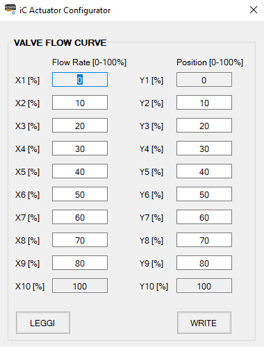
Flow rate SP X1
This register is used only if the actuator is assembled with a custom valve and set the first value of the flow rate at 0 (fixed value). This parameter with the following ones allows to building the custom valve characteristic curve.
Modbus register: 41080
BACnet object: analog value, object ID: 16, properties: present value.
Valve position Y1
This register is used only if the actuator is assembled with a custom valve and set the first value of the valve position at 0 (fixed value). This parameter with the following ones allows to building the custom valve characteristic curve.
Modbus register: 41081
BACnet object: analog value, object ID: 17, properties: present value.
Flow rate SP X2
This register is used only if the actuator is assembled with a custom valve and allow to set the second value of the flow rate (in percent) multiplied by ten. This parameter with the other ones allows to building the custom valve characteristic curve.
Modbus register: 41082
BACnet object: analog value, object ID: 18, properties: present value.
Valve position Y2
This register is used only if the actuator is assembled with a custom valve and allow to set the second value of the valve position (in percent) multiplied by ten. This parameter with the other ones allows to building the custom valve characteristic curve.
Modbus register: 41083
BACnet object: analog value, object ID: 19, properties: present value.
Flow rate SP X3
This register is used only if the actuator is assembled with a custom valve and allow to set the third value of the flow rate (in percent) multiplied by ten. This parameter with the other ones allows to building the custom valve characteristic curve.
Modbus register: 41084
BACnet object: analog value, object ID: 20, properties: present value.
Valve position Y3
This register is used only if the actuator is assembled with a custom valve and allow to set the third value of the valve position (in percent) multiplied by ten. This parameter with the other ones allows to building the custom valve characteristic curve.
Modbus register: 41085
BACnet object: analog value, object ID: 21, properties: present value.
Flow rate SP X4
This register is used only if the actuator is assembled with a custom valve and allow to set the fourth value of the flow rate (in percent) multiplied by ten. This parameter with the other ones allows to building the custom valve characteristic curve.
Modbus register: 41086
BACnet object: analog value, object ID: 22, properties: present value.
Valve position Y4
This register is used only if the actuator is assembled with a custom valve and allow to set the fourth value of the valve position (in percent) multiplied by ten. This parameter with the other ones, allows to building the custom valve characteristic curve.
Modbus register: 41087
BACnet object: analog value, object ID: 23, properties: present value.
Flow rate SP X5
This register is used only if the actuator is assembled with a custom valve and allow to set the fifth value of the flow rate (in percent) multiplied by ten. This parameter with the other ones allows to building the custom valve characteristic curve.
Modbus register: 41088
BACnet object: analog value, object ID: 24, properties: present value.
Valve position Y5
This register is used only if the actuator is assembled with a custom valve and allow to set the fifth value of the valve position (in percent) multiplied by ten. This parameter with the other ones allows to building the custom valve characteristic curve.
Modbus register: 41089
BACnet object: analog value, object ID: 25, properties: present value.
Flow rate SP X6
This register is used only if the actuator is assembled with a custom valve and allow to set the sixth value of the flow rate (in percent) multiplied by ten. This parameter with the other ones allows to building the custom valve characteristic curve.
Modbus register: 41090
BACnet object: analog value, object ID: 26, properties: present value.
Valve position Y6
This register is used only if the actuator is assembled with a custom valve and allow to set the sixth value of the valve position (in percent) multiplied by ten. This parameter with the other ones allows to building the custom valve characteristic curve.
Modbus register: 41091
BACnet object: analog value, object ID: 27, properties: present value.
Flow rate SP X7
This register is used only if the actuator is assembled with a custom valve and allow to set the seventh value of the flow rate (in percent) multiplied by ten. This parameter with the other ones allows to building the custom valve characteristic curve.
Modbus register: 41092
BACnet object: analog value, object ID: 28, properties: present value.
Valve position Y7
This register is used only if the actuator is assembled with a custom valve and allow to set the seventh value of the valve position (in percent) multiplied by ten. This parameter with the other ones allows to building the custom valve characteristic curve.
Modbus register: 41093
BACnet object: analog value, object ID: 29, properties: present value.
Flow rate SP X8
This register is used only if the actuator is assembled with a custom valve and allow to set the eighth value of the flow rate (in percent) multiplied by ten. This parameter with the other ones allows to building the custom valve characteristic curve.
Modbus register: 41094
BACnet object: analog value, object ID: 30, properties: present value.
Valve position Y8
This register is used only if the actuator is assembled with a custom valve and allow to set the eighth value of the valve position (in percent) multiplied by ten. This parameter with the other ones allows to building the custom valve characteristic curve.
Modbus register: 41095
BACnet object: analog value, object ID: 31, properties: present value.
Flow rate SP X9
This register is used only if the actuator is assembled with a custom valve and allow to set the nineth value of the flow rate (in percent) multiplied by ten. This parameter with the other ones allows to building the custom valve characteristic curve.
Modbus register: 41096
BACnet object: analog value, object ID: 32, properties: present value.
Valve position Y9
This register is used only if the actuator is assembled with a custom valve and allow to set the nineth value of the valve position (in percent) multiplied by ten. This parameter with the other ones allows to building the custom valve characteristic curve.
Modbus register: 41097
BACnet object: analog value, object ID: 33, properties: present value.
Flow rate SP X10
This register is used only if the actuator is assembled with a custom valve its value of the flow rate is set to the 100 (that multiplied by 10 is 1000) (fixed value). This parameter with the other ones allows to building the custom valve characteristic curve.
Modbus register: 41098
BACnet object: analog value, object ID: 34, properties: present value.
Valve position Y10
This register is used only if the actuator is assembled with a custom valve its value is set to the 100 (that multiplied by 10 is 1000) (fixed value). This parameter with the other ones allows to building the custom valve characteristic curve.
Modbus register: 41099
BACnet object: analog value, object ID: 35, properties: present value.
Indicated flow rate
This register calculates the indicated flow rate as m3/h (the value is multiplied by 100) for EBV/MVE-2-RS and as l/h (no multiplied factor) for MVC-2-RS.
Modbus register: 31100
BACnet object: analog value, object ID: 36, properties: present value.
Setpoints Section
Setpoint ΔT Control Heating (°C)
This register contains the value of the setpoint for the heating ΔT control loop.
The value contained in the register is multiplied by 10.
Modbus register: 41101
BACnet object: analog value, object ID: 37, properties: present value.
Setpoint ΔT Control Cooling (°C)
This register contains the value of the setpoint for the cooling ΔT control loop.
The value contained in the register is multiplied by 10.
Modbus register: 41102
BACnet object: analog value, object ID: 38, properties: present value.
Setpoint Supply Temperature Control Heating (°C)
This register contains the value of the setpoint for the heating supply temperature loop.
The value contained in the register is multiplied by 10.
Modbus register: 41103
BACnet object: analog value, object ID: 39, properties: present value.
Setpoint Supply Temperature Control Cooling (°C)
This register contains the value of the setpoint for the cooling supply temperature loop.
The value contained in the register is multiplied by 10.
Modbus register: 41104
BACnet object: analog value, object ID: 40, properties: present value.
Setpoint Supply Temperature Control Heating (°C)
This register contains the value of the setpoint for the heating return temperature loop.
The value contained in the register is multiplied by 10.
Modbus register: 41105
BACnet object: analog value, object ID: 41, properties: present value.
Setpoint Supply Temperature Control Cooling (°C)
This register contains the value of the setpoint for the cooling return temperature loop.
The value contained in the register is multiplied by 10.
Modbus register: 41106
BACnet object: analog value, object ID: 42, properties: present value.
Setpoint Minimum ΔT Heating (°C)
This register contains the value of the setpoint for the heating ΔT limitation loop.
The value contained in the register is multiplied by 10.
Modbus register: 41107
BACnet object: analog value, object ID: 43, properties: present value.
Setpoint Minimum ΔT Cooling (°C)
This register contains the value of the setpoint for the cooling ΔT limitation loop.
The value contained in the register is multiplied by 10.
Modbus register: 41108
BACnet object: analog value, object ID: 44, properties: present value.
Setpoint Max. Supply Temperature Heating (°C)
This register contains the value of the setpoint for the heating supply temperature limitation loop.
The value contained in the register is multiplied by 10.
Modbus register: 41109
BACnet object: analog value, object ID: 45, properties: present value.
Setpoint Min. Supply Temperature Cooling (°C)
This register contains the value of the setpoint for the cooling supply temperature limitation loop.
The value contained in the register is multiplied by 10.
Modbus register: 41110
BACnet object: analog value, object ID: 46, properties: present value.
Setpoint Max. Return Temperature Heating (°C)
This register contains the value of the setpoint for the heating return temperature limitation loop.
The value contained in the register is multiplied by 10.
Modbus register: 41111
BACnet object: analog value, object ID: 47, properties: present value.
Setpoint Min. Return Temperature Cooling (°C)
This register contains the value of the setpoint for the cooling return temperature limitation loop.
The value contained in the register is multiplied by 10.
Modbus register: 41112
BACnet object: analog value, object ID: 48, properties: present value.
Power Control/Limit Section
Design Power
This register allows to set the maximum power control, this value is multiplied by 10 (kW).
Modbus register: 41113
BACnet object: analog value, object ID: 49, properties: present value.
Set Max Power Limit
This register allows to set the maximum power limit, this value is multiplied by 10 (kW).
Modbus register: 41114
BACnet object: analog value, object ID: 50, properties: present value.
Temperature Sensors Section
Supply Temperature (°C)
This register contains the supply temperature value. The value stored in the register is multiplied by 10.
If the sensor is disconnected or faulty, the stored value is 5000.
Modbus register: 31115
BACnet object: analog input, object ID: 0, properties: present value.
Return Temperature (°C)
This register contains the return temperature value.
The value stored in the register is multiplied by 10.
If the sensor is disconnected or faulty, the stored value is 5000.
Modbus register: 31116
BACnet object: analog input, object ID: 1, properties: present value.
ΔT (°C)
This register contains the value of the difference between the supply and return temperatures (ΔT).
The value stored in the register is multiplied by 10.
If the supply and/or return temperature sensor is disconnected or faulty, the stored value is 5000.
Modbus register: 31117
BACnet object: analog value, object ID: 51, properties: present value.
Energy Heating/Cooling Section
Instant power
This register calculates the instant power (kW*10).
Modbus register: 31120
BACnet object: analog value, object ID: 52, properties: present value.
Heating energy LSR
This register contains the least significant data of the total calculated heating energy (kWh*10).
Modbus register: 31121
BACnet object: analog value, object ID: 53, properties: present value.
Heating energy MSR
This register contains the most significant data of the total calculated heating energy (kWh*10).
Modbus register: 31122
BACnet object: analog value, object ID: 53, properties: present value.
Cooling energy LSR
This register contains the least significant data of the total calculated cooling energy (kWh*10).
Modbus register: 31123
BACnet object: analog value, object ID: 54, properties: present value.
Cooling energy MSR
This register contains the most significant data of the total calculated cooling energy (kWh*10).
Modbus register: 31124
BACnet object: analog value, object ID: 54, properties: present value.
Heating energy at 31/12 LSR
This register allows to read for the least significant data of the total heating energy (kWh*10) at the end of the year.
Modbus register: 31139
BACnet object: analog value, object ID: 55, properties: present value.
Heating energy at 31/12 MSR
This register allows to read for the most significant data of the total heating energy (kWh*10) at the end of the year.
Modbus register: 31140
BACnet object: analog value, object ID: 55, properties: present value.
Heating energy value 1
This register contains the energy (heating) consumption (MWh*10) for the month of January.
Modbus register: 31141
BACnet object: analog value, object ID: 56, properties: present value.
Heating energy value 2
This register contains the energy (heating) consumption (MWh*10) for the month of February.
Modbus register: 31142
BACnet object: analog value, object ID: 57, properties: present value.
Heating energy value 3
This register contains the energy (heating) consumption (MWh*10) for the month of March.
Modbus register: 31143
BACnet object: analog value, object ID: 58, properties: present value.
Heating energy value 4
This register contains the energy (heating) consumption (MWh*10) for the month of April.
Modbus register: 31144
BACnet object: analog value, object ID: 59, properties: present value.
Heating energy value 5
This register contains the energy (heating) consumption (MWh*10) for the month of May.
Modbus register: 31145
BACnet object: analog value, object ID: 60, properties: present value.
Heating energy value 6
This register contains the energy (heating) consumption (MWh*10) for the month of June.
Modbus register: 31146
BACnet object: analog value, object ID: 61, properties: present value.
Heating energy value 7
This register contains the energy (heating) consumption (MWh*10) for the month of July.
Modbus register: 31147
BACnet object: analog value, object ID: 62, properties: present value.
Heating energy value 8
This register contains the energy (heating) consumption (MWh*10) for the month of August.
Modbus register: 31148
BACnet object: analog value, object ID: 63, properties: present value.
Heating energy value 9
This register contains the energy (heating) consumption (MWh*10) the month of September.
Modbus register: 31149
BACnet object: analog value, object ID: 64, properties: present value.
Heating energy value 10
This register contains the energy (heating) consumption (MWh*10) for the month of October.
Modbus register: 31150
BACnet object: analog value, object ID: 65, properties: present value.
Heating energy value 11
This register contains the energy (heating) consumption (MWh*10) for the month of November.
Modbus register: 31151
BACnet object: analog value, object ID: 66, properties: present value.
Heating energy value 12
This register contains the energy (heating) consumption (MWh*10) for the month of December.
Modbus register: 31152
BACnet object: analog value, object ID: 67, properties: present value.
Cooling energy at 31/12 LSR
This register allows to read the least significant data of the total cooling energy (kWh*10) at the end of the year.
Modbus register: 31153
BACnet object: analog value, object ID: 68, properties: present value.
Cooling energy at 31/12 MSR
This register contains the most significant data of the total cooling energy (kWh*10) at the end of the year.
Modbus register: 31154
BACnet object: analog value, object ID: 68, properties: present value.
Cooling energy value 1
This register contains the energy (cooling) consumption (MWh*10) for the month of January.
Modbus register: 31155
BACnet object: analog value, object ID: 69, properties: present value.
Cooling energy value 2
This register contains the energy (cooling) consumption (MWh*10) for the month of February.
Modbus register: 31156
BACnet object: analog value, object ID: 70, properties: present value.
Cooling energy value 3
This register contains the energy (cooling) consumption (MWh*10) for the month of March.
Modbus register: 31157
BACnet object: analog value, object ID: 71, properties: present value.
Cooling energy value 4
This register contains the energy (cooling) consumption (MWh*10) for the month of April.
Modbus register: 31158
BACnet object: analog value, object ID: 72, properties: present value.
Cooling energy value 5
This register contains the energy (cooling) consumption (MWh*10) for the month of May.
Modbus register: 31159
BACnet object: analog value, object ID: 73, properties: present value.
Cooling energy value 6
This register contains the energy (cooling) consumption (MWh*10) for the month of June.
Modbus register: 31160
BACnet object: analog value, object ID: 74, properties: present value.
Cooling energy value 7
This register contains the energy (cooling) consumption (MWh*10) for the month of July.
Modbus register: 31161
BACnet object: analog value, object ID: 75, properties: present value.
Cooling energy value 8
This register contains the energy (cooling) consumption (MWh*10) for the month of August.
Modbus register: 31162
BACnet object: analog value, object ID: 76, properties: present value.
Cooling energy value 9
This register contains the energy (cooling) consumption (MWh*10) for the month of September.
Modbus register: 31163
BACnet object: analog value, object ID: 77, properties: present value.
Cooling energy value 10
This register contains the energy (cooling) consumption (MWh*10) for the month of October.
Modbus register: 31164
BACnet object: analog value, object ID: 78, properties: present value.
Cooling energy value 11
This register contains the energy (cooling) consumption (MWh*10) for the month of November.
Modbus register: 31165
BACnet object: analog value, object ID: 79, properties: present value.
Cooling energy value 12
This register contains the energy (cooling) consumption (MWh*10) for the month of December.
Modbus register: 31166
BACnet object: analog value, object ID: 80, properties: present value.
Clock Function Section
Clock Minutes
This database register contains the value of the minutes received during the time synchronization phase.
Modbus register: 41182
BACnet object:
|
Analog value object |
Device object |
||
|---|---|---|---|
|
Object ID |
Property |
Object ID |
Property |
|
81 |
Present value |
1 |
Local time |
Clock Minutes object in BACnet
Clock Hours
This register contains the value of the hours received during the time synchronization phase.
Modbus register: 41183
BACnet object:
|
Analog value object |
Device object |
||
|---|---|---|---|
|
Object ID |
Property |
Object ID |
Property |
|
82 |
Present value |
1 |
Local time |
Clock Hours object in BACnet
Clock Day
This register contains the value of the day received during the time synchronization phase.
Modbus register: 41184
BACnet object:
|
Analog value object |
Device object |
||
|---|---|---|---|
|
Object ID |
Property |
Object ID |
Property |
|
83 |
Present value |
1 |
Local date |
Clock Day object in BACnet
Clock Month
This register contains the value of the month received during the time synchronization phase.
Modbus register: 41185
BACnet object:
|
Analog value object |
Device object |
||
|---|---|---|---|
|
Object ID |
Property |
Object ID |
Property |
|
84 |
Present value |
1 |
Local date |
Clock Month object in BACnet
Clock Year
This register contains the value of the year received during the time synchronization phase.
Registers from address 1181 to address 1185 contain the values that store the date and time of the actuator once they have been synchronized (only necessary in the case of energy calculation).
The actuator doesn’t have a “buffer” battery so that every time it is turned off or reset the date and time are lost, a new synchronization will therefore be required. If the date and time are not synchronized, the default date/time is: 01/01/2000 00:00.
Modbus register: 41186
BACnet object:
|
Analog value object |
Device object |
||
|---|---|---|---|
|
Object ID |
Property |
Object ID |
Property |
|
85 |
Present value |
1 |
Local date |
Clock Year object in BACnet
Loop Output Section
Loop Output Dynamic Balancing (EBV only)
This register contains the percentage output value of the dynamic balancing loop.
The value inside the register is multiplied by 10.
Modbus register: 31192
Loop Output BMS (%)
This register contains the percentage output value of the BMS loop.
The value inside the register is multiplied by 10.
Modbus register: 31193
Loop Output flow rate control (MVE/MVC-2-RS only)
This register contains the percentage output value of the output flow rate control loop.
The value inside the register is multiplied by 10.
Modbus register: 31194
Loop Output power
This register contains the percentage output value of the power loop.
If one or both of the temperature sensors are disconnected or faulty, the stored value is 65535.
The value inside the register is multiplied by 10.
Modbus register: 31196
Loop Output power limit
This register contains the percentage output value of the power limit loop.
If one or both of the temperature sensors are disconnected or faulty, the stored value is 65535.
The value inside the register is multiplied by 10.
Modbus register: 31197
Loop Output Temperature Control (%)
This register contains the percentage output value of the Temperature control loop.
If one or both of the temperature sensors are disconnected or faulty, the stored value is 5000.
The value inside the register is multiplied by 10.
Modbus register: 31198
Loop Output Temperature Limitations (%)
This register contains the percentage output value of the Temperature limit loop.
If one or both of the temperature sensors are disconnected or faulty, the stored value is 5000.
The value inside the register is multiplied by 10.
Modbus register: 31199
Operating loop output (%)
This register contains the percentage out value of the operating loop resulting from the actually enabled functions.
The value inside the register is multiplied by 10.
Modbus register: 31200
Power Section
Max. power
This register allows to set of the valve nominal power (kW*10).
Modbus register: 41207
BACnet object: analog value, object ID: 86, properties: present value.
Media density
This register allows to set the density of the fluid, the default value is for water at 20°C (997.8 Kg/m3). The value is multiplied by 10, so in the register is: 9978.
The maximum value is 6553.5.
Modbus register: 41208
BACnet object: analog value, object ID: 87, properties: present value.
Media specific heat
This database register allows to set the specific heat of the fluid, the default value is for water at 20°C (4196 J/Kg °C). The value is multiplied by 10, so in the register is: 41960.
The maximum value is 6553.5.
Modbus register: 41209
BACnet object: analog value, object ID: 88, properties: present value.
Custom nominal power ΔT 20K
This register contains the valve nominal power at 20°C (kW*10).
Modbus register: 31213
Loop Parameters Section
Action Type
This database register contains the type of loop action that can be:
|
Addr.1230 |
Action type |
|---|---|
|
0 |
Proportional (P) |
|
1 |
Proportional Integral (PI) |
|
2 |
Proportional Integral Derivative (PID) |
Selection of the action type
Modbus register: 41231
BACnet object: multi state value, object ID: 8, properties: present value.
Derivative Time
This register contains the derivative time of the derivative action expressed as "gain" from 1 to 10 (default value is 1).
Modbus register: 41232
BACnet object: analog value, object ID: 89, properties: present value.
Integral Time (min)
This register contains the integral time of the integral action expressed in minutes from 0 to 30.
Modbus register: 41233
BACnet object: analog value, object ID: 90, properties: present value.
Proportional Bandwidth (°C)
This register contains the proportional bandwidth for all loops. The value stored in the register is multiplied by 10, so the range is from 0 to 100 (from 0 to 10°C)
Modbus register: 41234
BACnet object: analog value, object ID: 91, properties: present value.
Month timestamp of 31st December
This register allows to read the year end month total energy, it is set to December.
Modbus register: 31241
BACnet object: analog value, object ID: 92, properties: present value.
Year timestamp of 31st December
This register allows to read the year of the last reading recorded on 31 December.
Modbus register: 31242
BACnet object: analog value, object ID: 93, properties: present value.
Month timestamp of value 1
This register contains the month in which the actuator has registered the energy consumption, it is set to January.
Modbus register: 31243
BACnet object: analog value, object ID: 94, properties: present value.
Year timestamp of value 1
This register contains the year in which the actuator has registered the energy consumption in January.
Modbus register: 31244
BACnet object: analog value, object ID: 95, properties: present value.
Month timestamp of value 2
This register contains the month in which the actuator has registered the energy consumption, it is set to February.
Modbus register: 31245
BACnet object: analog value, object ID: 96, properties: present value.
Year timestamp of value 2
This register contains the year in which the actuator has registered the energy consumption in February.
Modbus register: 31246
BACnet object: analog value, object ID: 97, properties: present value.
Month timestamp of value 3
This register contains the month in which the actuator has registered the energy consumption, it is set to March.
Modbus register: 31247
BACnet object: analog value, object ID: 98, properties: present value.
Year timestamp of value 3
This register contains the year in which the actuator has registered the energy consumption in March.
Modbus register: 31248
BACnet object: analog value, object ID: 99, properties: present value.
Month timestamp of value 4
This register contains the month in which the actuator has registered the energy consumption, it is set to April.
Modbus register: 31249
BACnet object: analog value, object ID: 100, properties: present value.
Year timestamp of value 4
This register contains the year in which the actuator has registered the energy consumption in April.
Modbus register: 31250
BACnet object: analog value, object ID: 101, properties: present value.
Month timestamp of value 5
This register contains the month in which the actuator has registered the energy consumption, it is set to May.
Modbus register: 31251
BACnet object: analog value, object ID: 102, properties: present value.
Year timestamp of value 5
This register contains the year in which the actuator has registered the energy consumption in May.
Modbus register: 31252
BACnet object: analog value, object ID: 103, properties: present value.
Month timestamp of value 6
This register contains the month in which the actuator has registered the energy consumption, it is set to June.
Modbus register: 31253
BACnet object: analog value, object ID: 104, properties: present value.
Year timestamp of value 6
This register contains the year in which the actuator has registered the energy consumption in June.
Modbus register: 31254
BACnet object: analog value, object ID: 105, properties: present value.
Month timestamp of value 7
This register contains the month in which the actuator has registered the energy consumption, it is set to July.
Modbus register: 31255
BACnet object: analog value, object ID: 106, properties: present value.
Year timestamp of value 7
This register contains the year in which the actuator has registered the energy consumption in July.
Modbus register: 31256
BACnet object: analog value, object ID: 107, properties: present value.
Month timestamp of value 8
This register contains the month in which the actuator has registered the energy consumption, it is set to August.
Modbus register: 31257
BACnet object: analog value, object ID: 108, properties: present value.
Year timestamp of value 8
This register contains the year in which the actuator has registered the energy consumption in August.
Modbus register: 31258
BACnet object: analog value, object ID: 109, properties: present value.
Month timestamp of value 9
This register contains the month in which the actuator has registered the energy consumption, it is set to September.
Modbus register: 31259
BACnet object: analog value, object ID: 110, properties: present value.
Year timestamp of value 9
This register contains the year in which the actuator has registered the energy consumption in September.
Modbus register: 31260
BACnet object: analog value, object ID: 111, properties: present value.
Month timestamp of value 10
This register contains the month in which the actuator has registered the energy consumption, it is set to October.
Modbus register: 31261
BACnet object: analog value, object ID: 112, properties: present value.
Year timestamp of value 10
This register contains the year in which the actuator has registered the energy consumption in October.
Modbus register: 31262
BACnet object: analog value, object ID: 113, properties: present value.
Month timestamp of value 11
This register contains the month in which the actuator has registered the energy consumption, it is set to November.
Modbus register: 31263
BACnet object: analog value, object ID: 114, properties: present value.
Year timestamp of value 11
This register contains the year in which the actuator has registered the energy consumption in November.
Modbus register: 31264
BACnet object: analog value, object ID: 115, properties: present value.
Month timestamp of value 12
This register contains the month in which the actuator has registered the energy consumption, it is set to December.
Modbus register: 31265
BACnet object: analog value, object ID: 116, properties: present value.
Year timestamp of value 12
This register contains the year in which the actuator has registered the energy consumption in December.
Modbus register: 31266
BACnet object: analog value, object ID: 117, properties: present value.