The article outlines how to configure a Fox(s) communication on a station to enable opening of views added in a remote device (for example, in the “Supervisor”, opening graphics created in the iSMA-B-MAC36NL controller without a need to multiply files, import points, and redo all “bindings”).
First, it is required to properly establish a basic Fox(s) communication between two stations (one way is sufficient - a connection created in an importing device - in the described example, on the “Supervisor’s” side), which is not covered in this article.
1. Preparing a station containing views
In this stage, it is required to create “PX” views on one station with setting the “binding” value. Views will be later sent to the second station. For the purposes of this article, the following station has been created:
|
No. |
Name and Location of the File |
View Name |
View Location |
Detailed Characteristics of the File |
|---|---|---|---|---|
|
1 |
“files/px/Test.px” |
“Test View” |
“Config/TestLogic” |
Simple view with “binding” to points, no graphic files. |
|
2 |
“files/px/Home.px” |
“Home Page” |
“Config/HomeLogic” |
View with graphic files (both relating to files in the local station and “jar” modules; “PNG” and “SVG” formats are checked) and with “binding” to points. |
|
3 |
“files/px/RoomTypeA.px” and (as “PxInclude”)
|
“Room 101” |
“Config/Room101Logic” |
View with:
Graphic files, both in the “PxInclude” and in the main view (of “PNG” and “SVG”) - regard the “jar” module and station’s local files. |
Table 1. List of view created in the described example with their characteristics
Having created graphics according to the above criteria, the station has the following contents:
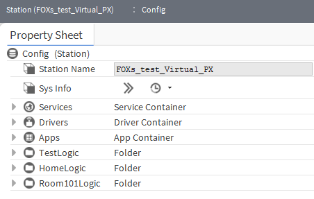
Figure 1. Structure of folders of the iSMA-B-MAC36NL controller’s station
With the following station files:
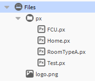
Figure 2. List of the “PX” files of the iSMA-B-MAC36NL controller’s station
1.1. Configuration of the “Test.px” file
The “Test.px” file is presented below. The file contains basic widgets such as buttons and labels. However, the ‘binding’ to points is relative (e.g., “slot:BooleanWritable”).

Figure 3. Contents of the “Test.px” file
1.2. Configuration of the “Home.px” file
The “Home.px” file is presented below. The file contains not only basic widgets such as buttons and labels but also widgets referring to graphic files in the “jar” modules (e.g., buttons) or in the local station’s files (e.g., “logo.png”). Also, a graphic referring to the “jar” modules is included in the “CanvasPane” background. The “binding” to points is absolute (e.g., “station:|slot:/HomeLogic/AHU”).
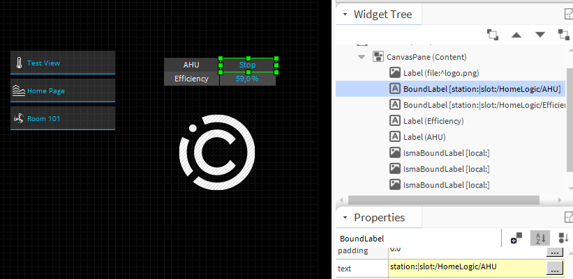
Figure 4. Contents of the “Home.px” file
1.3. Configuration of the “RoomTypeA.px” and “FCU.px” files
The “RoomTypeA.px” file (apart from basic widgets such as button and labels) contains a graphic widget with the “BQL” query and the “FCU.px” file located in the “PxIncluce” widget. The “bindings” in the “FCU.px” file are presented below:
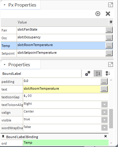
Figure 5. Proper configuration of “binding” in the “FCU.px” file using “PxProperties” variables
WARNING: Locally, the below configuration method is also possible, however, it is inadequate for the “Virtual PX” mechanism over the Fox(s) communication:
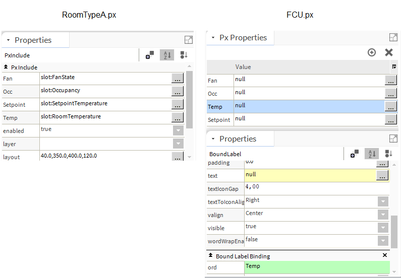
Figure 6. Improper configuration of “binding” in the “RoomTypeA.px” and “FCU.px” files using the “PxProperties” variables
For proper sending of the “PX” file containing a graphic widget with the “BQL” query, it is required to add the “report.jar” module to the device. Then, add the “ReportService” from the “report” palette to station’s services, and next add the “BqlGrid” component there. The query (in the “Query” slot), used in the given example, is “station:|slot:/|bql:select name, out from control:NumericPoint”. A propoer configuration is presented below:

Figure 7. Proper configuration of the “Bql” query using the “BqlGrid” and “ReportService”
In the next step, go to the editing mode, where the table with the “Bql” query is going to be located. In the editing mode, drag&drop the “BqlGrid” component from the “navTree” to the working area. The “Make Widget” pop-up window appears. Click the “Workbench View” option in the pop-up window, and select of of three system views:
-
“AX Grid Table” (selected in the described example),
-
“Grid Label Pane”,
-
“Grid Table”.
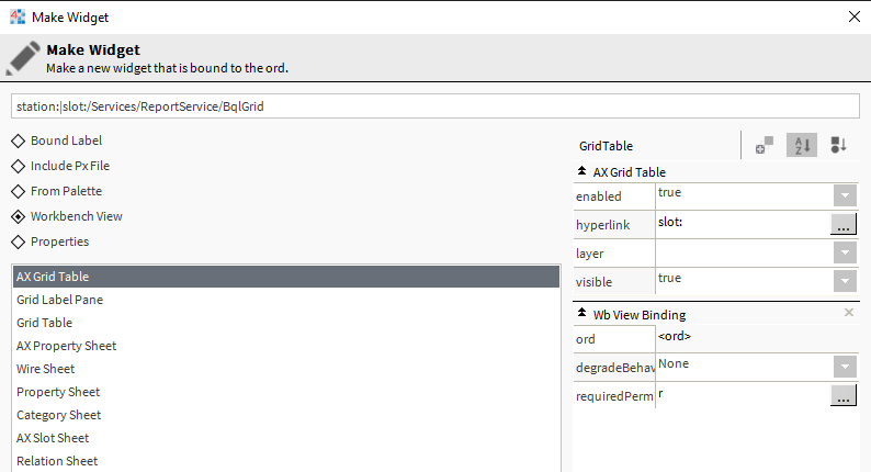
Figure 8. Selecting the system view in the “Make Widget” pop-up window
WARNING: Locally, it is also possible to carry out the configuration using the “BoundTable” widget from the “bajaui” palette. Unfortunately, the “BoundTable” does not display any values if opened as a “Virtual Px” view (transferred with the “Fox(s)” protocol).
Having properly configured both files, the view is presented as follows:

Figure 9. Contents of the “RoomTypeA.px” and “FCU.px” files
WARNING: As of 2020-03-30, there has been a bug recognized (Error rendering macro 'jira' : null ) in the “iSMA_Graphics”, preventing the “VirtualPx” parser from extracting graphics with the “IsmaBoundLabel” and “IsmaPicture” widgets.
2. Preparing a station importing views as “Virtual Px”
Provided the proper communication with the station has been established, it is required to edit it, and set the “Virtual Enabled” slot to true, as presented below:
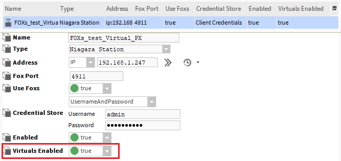
Figure 10. Enabling to send points and virtual files from a remote station with the Fox(s) protocol
This enables to send virtual “PX” views and virtual points, which are not included in the “Network Point” license limitation (“Global Capacity”), and to check their current values online.
WARNING: Virtual points of the remote device cannot be linked to the logic in the local station.
After setting the “Virtual Enabled” slot, it can be moved to the “Virtual” subfolder (in the described example: “Config/Drivers/NiagaraNetwork/FOXs_test_Virtual_PX/Virtual”); for the first time, the file can take longer to load (due to synchronization of virtual files and points). After the process is finished, the following contents are displayed:

Figure 11. Contents of the “Virtual” subfolder from the iSMA-B-MAC36NL device displayed in the “Supervisor” station
Double-clicking one of the folders with views automatically creates a configuration of synchronization of relevant graphic and “PX” files, synchronizes them, and, finally, opens the contents of the remote station view, as presented below:

Figure 12. The “Test View” virtual view in the “Supervisor” station synchronized with the iSMA-B-MAC36NL device
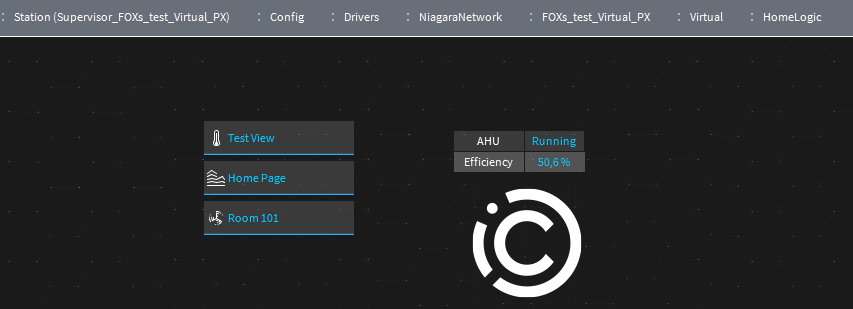
Figure 13. The “Home Page” virtual view in the “Supervisor” station synchronized with the iSMA-B-MAC36NL device
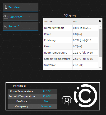
Figure 14. The “Room 101” virtual view in the “Supervisor” station synchronized with the iSMA-B-MAC36NL device
3. Updating virtual views
If the PX files were edited in a home station after having configured them in a remote station (e.g., “Supervisor”) as “Virtual Px”, it is required to perform a manual synchronization of files. Go to the “Virtual” subfolder in the remote station (in the described example: “Config/Drivers/NiagaraNetwork/FOXs_test_Virtual_PX/Virtual”), and right-click the folder with the view to be synchronized. Select “Actions” from the context menu, and then - “Reload Virtual Px Views”, as presented below:
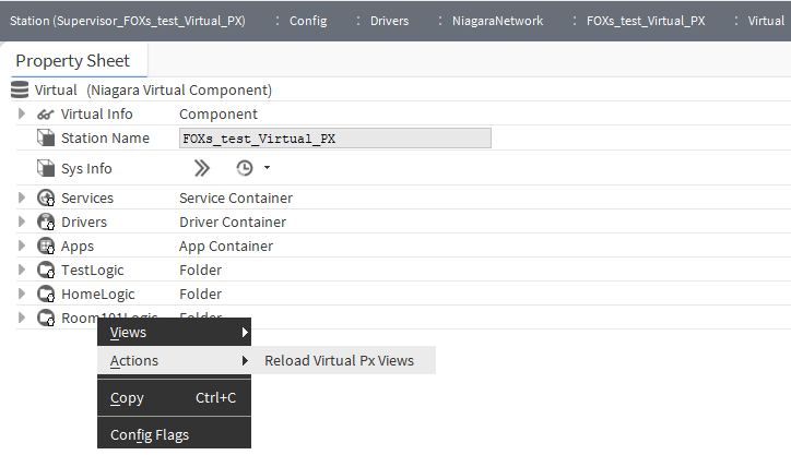
Figure15. Manual synchronization of the “PX” views
Invoking this action is preceded with a warning, which has to be accepted, and then all view files included in the folder are synchronized.
4. Configuration of virtual policies of views/points in the importing station
Furthermore, it is possible to set an individual configuration of “Virtual Policies”, which is located directly in the “NiagaraNetowrk” component:

Figure 16. Configuration of the “Virtual Polices” in the “NiagaraNetwork” component
The following elements are, among others, possible to be changed:
-
type and enabling of sustaining cache,
-
way of synchronizing changes in the “PX” files;
-
local storage of “PX” files copies and referred graphic files or videos.
