Setting Modbus Address
To determine the address on the Modbus network, the device has two rotary switches, S1 and S2, located on the top panel of the device.
It is possible to set the device address from 0 to 99.
The formula for setting the address is as follows:
Address = S2 • 10 + S1,
where S1 and S2 are values of switches.
For example:
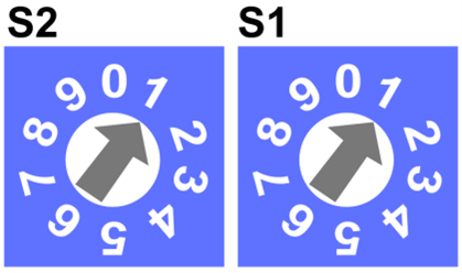
Setting Modbus address with rotary switches
Switches set as in figure above will set the device address to 11.
Setting Baud Rate
Transmission baud rate is determined by the S3 DIP switch (sections 1, 2 and 3) in accordance with the following table:
|
1 |
2 |
3 |
Baud Rate |
|---|---|---|---|
|
Off (0) |
Off (0) |
Off (0) |
Defined by the user in the register |
|
Off (0) |
Off (0) |
On (1) |
76800 |
|
Off (0) |
On (1) |
Off (0) |
4800 |
|
Off (0) |
On (1) |
On (1) |
9600 |
|
On (1) |
Off (0) |
Off (0) |
19200 |
|
On (1) |
Off (0) |
On (1) |
38400 |
|
On (1) |
On (1) |
Off (0) |
57600 |
|
On (1) |
On (1) |
On (1) |
115200 (factory set) |
Setting baud rate
Setting Protocol
Protocol selection is made by sections 4 and 5 of the S3 DIP switch according to the table:
|
4 |
5 |
Protocol |
|---|---|---|
|
Off (0) |
Off (0) |
Modbus RTU |
|
Off (0) |
On (1) |
Modbus ASCII |
|
On (1) |
Off (0) |
N/A |
|
On (1) |
On (1) |
N/A |
Setting protocol
Free Modbus TCP Sockets Counter
Note:
The free Modbus TCP sockets counter is implemented from the 3.0 firmware.
The counter of free Modbus TCP sockets informs the user about the number of available Modbus TCP connections for the device.
The maximum number of TCP connections is 4.
The number of free Modbus TCP sockets can be reached in two ways:
-
in the 292 Modbus register (read-only): the register shows values from 0 to 4, where 0 means no available connections, 4 means 4 available connections;
-
in the IP Configuration tab in the web server.