This article shows how to adapt the default iSMA-B-FCU application to the fan coil using the 'DIP switch'.
-
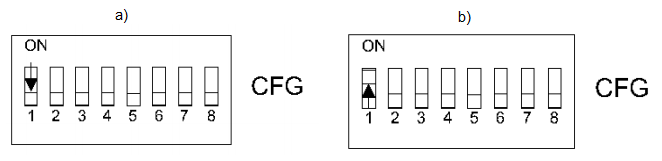
Pipe mode system - 'DIP switch' number 1, depending on the position, is used to select two-pipe mode ('DIP switch' to 'ON') and four-pipe mode ('DIP switch' to 'OFF').
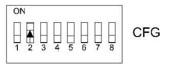
2. The second level of heating - 'DIP switch' number 2 is used to turn on the second level of heating.
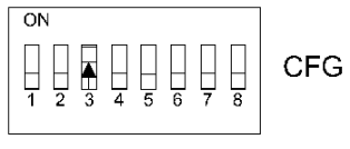
3. The second stage of cooling - 'DIP switch' number 3 is used to switch on the second stage of cooling.
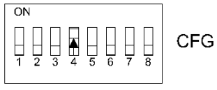
4. Heating/cooling mode - 'DIP switch' number 4 is used to switch heating/cooling into the digital or analog mode.
5. CV temperature source - 'DIP switch' number 5, 6 is used to select the source from which iSMA-B-FCU is to receive information about the temperature in a given room.
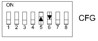
Description of available sources:
-
Room panel - the temperature level is collected from iSMA-B-LP room panel connected to iSMA-B-FCU device via the RJ12 socket (5 switch 'OFF' 6 switch 'OFF'),
-
Room sensor - the temperature level is collected from the sensor connected to the special input S3 (5 switch 'OFF', 6 switch 'ON'),
-
Temp. Return air - the temperature level is collected from the sensor connected to the special input S1 (5 switch 'ON, 6 switch 'OFF'),
-
Network temperature - the temperature level is collected from the network variable of the second iSMA-B-FCU operating in the Master-Slave mode (5 switch 'ON', 6 switch 'ON');
6. Fan type - ‘DIP switch’ numbers 7, 8 are used to select the type of fans.
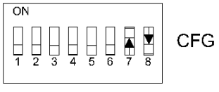
Description of the fan types:
-
Analog type (0-10V) (7 switch 'OFF', 8 switch 'OFF'),
-
Single-speed type (7 switch 'OFF', 8 switch 'ON'),
-
Two-speed type (7 switch 'ON', 8 switch 'OFF'),
-
Three-speed type (7 switch 'ON', 8 switch 'ON');
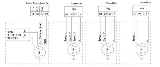
Picture 1. Fan motor connection according to fan control mode.
Table with all ‘DIP switch’ configurations:
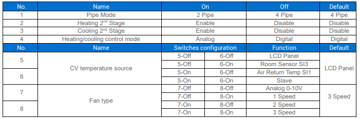
Table 1. General DIP switch configuration in iSMA-B-FCU.