.png?cb=93cc9c54d841cd4deabf9014f24ce066)
Front panel
USB1 Port
The device is equipped with a built-in mini USB port dedicated for managing controller firmware and for diagnostics.
The USB1 port provides also the power supply for device, which might be useful during the process of starting front panel LED functions.
WARNING! If the USB1 port is used as the power supply for the device, it is not possible to commission and/or to manage DALI network(s)!
LED
The device is equipped with four LEDs for quick status checking and diagnostics:
-
The power LED ON lights up (green) and then turns the power supply on.
-
The communication LED COM1 lights up (orange) for 20 ms after receiving/sending each package through the main RS485 port. As long as the device receives/sends packages, the communication LED blinks continuously.
DIP Switches
The iSMA-B-2D1B device is equipped with 3 DIP switches on its front panel:
-
6-position S1 - PROTOCOL DIP switch;
-
8-position S2 - MAC DIP switch;
-
8-position S3 - CFG DIP switch.
S1 PROTOCOL DIP Switch: Baud Rate Selection
Transmission baud rate is determined by the S1 switch (sections 1, 2, and 3) in accordance with the following table:
|
1 |
2 |
3 |
Baud Rate |
|---|---|---|---|
|
OFF (0) |
OFF (0) |
OFF (0) |
Defined by the user |
|
OFF (0) |
OFF (0) |
ON (1) |
76800 |
|
OFF (0) |
ON (1) |
OFF (0) |
4800 |
|
OFF (0) |
ON (1) |
ON (1) |
9600 |
|
ON (1) |
OFF (0) |
OFF (0) |
19200 |
|
ON (1) |
OFF (0) |
ON (1) |
38400 |
|
ON (1) |
ON (1) |
OFF (0) |
57600 |
|
ON (1) |
ON (1) |
ON (1) |
115200 |
Baud rate selection
S1 PROTOCOL DIP Switch: Protocol Selection
Protocol selection is performed with sections 4 and 5 of the S1 DIP switch in accordance with the table below:
|
4 |
5 |
Protocol |
|---|---|---|
|
OFF (0) |
OFF (0) |
Modbus RTU |
|
OFF (0) |
ON (1) |
Modbus ASCII |
Protocol selection
S2 MAC DIP Switch: Setting Controller Address
The controller address is setting using the S2 MAC DIP switch. The way of setting the address is presented in the below figure and table. The whole addressing table is presented in the separate chapter MAC DIP SWITCH addressing table.

MAC DIP switch
|
Switch No. |
Position |
Function |
|---|---|---|
|
1 |
On |
Add 1 to Address |
|
Off |
Add 0 to Address |
|
|
2 |
On |
Add 2 to Address |
|
Off |
Add 0 to Address |
|
|
3 |
On |
Add 4 to Address |
|
Off |
Add 0 to Address |
|
|
4 |
On |
Add 8 to Address |
|
Off |
Add 0 to Address |
|
|
5 |
On |
Add 16 to Address |
|
Off |
Add 0 to Address |
|
|
6 |
On |
Add 32 to Address |
|
Off |
Add 0 to Address |
|
|
7 |
On |
Add 64 to Address |
|
Off |
Add 0 to Address |
|
|
8 |
On |
Add 128 to Address |
|
Off |
Add 0 to Address |
Setting an address with the MAC DIP switch
Example: Setting the address to 83
Address 83 contains the following multiplicity of the number 2:
83 = 1 + 2 + 16 + 64.
The MAC DIP switch settings are presented in the table below.
|
Address |
S1 |
S2 |
S3 |
S4 |
S5 |
S6 |
S7 |
S8 |
|---|---|---|---|---|---|---|---|---|
|
83 |
On |
On |
|
|
On |
|
On |
|
Configuration of the MAC DIP switch for an 83 address
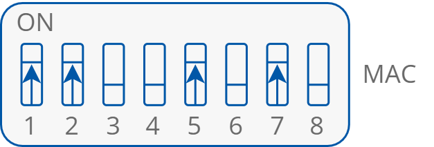
Setting an 83 address on the MAC DIP switch
WARNING! Do not set address 255 (all switches in on position). This address setting is reserved for system operation.
S3 CFG DIP Switch
The device is equipped with an 8-position CFG DIP switch on the top panel. Each segment of the CFG determines the operation mode, including the operating of special and digital inputs according to the interactions with the outputs.
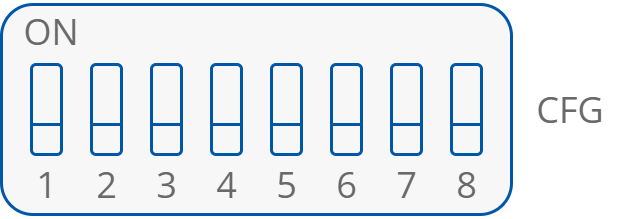
CFG DIP switch
The relation between particular inputs and outputs with the assigned CFG DIP switch configuration is presented in the table below:
|
DIP Switch No. |
Position |
Function |
Description |
|---|---|---|---|
|
1 |
On |
Bistable switches connected to digital inputs I1, I2 |
Changing between bistable and monostable switches connected to the digital input no. 1 and 2 |
|
Off |
Monostable switches connected to Digital Inputs I1, I2 |
||
|
2 |
On |
Digital input I1 controls DALI1 and DALI2 networks |
Changing between the control modes of the digital input no. 1 |
|
Off |
Digital input I1 controls only DALI1 network |
||
|
3 |
On |
Special input SI1 controls DALI1 and DALI2 networks |
Changing between the control modes of the special input no. 1 |
|
Off |
Special input SI1 controls only DALI1 network |
||
|
4 |
On |
Digital input I2 controls DALI1 and DALI2 networks |
Changing between the control modes of the digital input no. 2 |
|
Off |
Digital input I2 controls only DALI2 network |
||
|
5 |
On |
Special input SI2 controls DALI1 and DALI2 networks |
Changing between the control modes of the special input no. 2 |
|
Off |
Special input SI2 controls only DALI2 network |
||
|
6 |
On |
Light control with light outputs |
Changing between light control modes |
|
Off |
Light control with DALI |
||
|
7 |
On |
Bistable switches connected to digital inputs I3, I4 |
Changing between bistable and monostable switches connected to the digital input no. 3 and 4 |
|
Off |
Monostable switches connected to digital inputs I3, I4 |
||
|
8 |
On |
Light level control mode activated |
Changing light level control mode activation |
|
Off |
Light level control mode inactive |
The CFG DIP switch configuration