Issue
There is no communication with a slave device despite having correctly added the ModbusAsyncNetwork and ModbusAsyncDevice components to the MAC36NL station.
Possible causes and solutions
-
Wrong configuration of the serial port
-
Communication parameters are not properly set for devices on the bus
-
MAC36NL-RS - the COM2 RS485 port is not working
-
Attempt to ping the device's register which is a part of a larger variable
-
No support for 0x03 or 0x04 functions of the Modbus RTU slave device
-
Wrong or no answer from the Modbus RTU slave device
-
Read 32-bit value is not compliant with the value in the remote device
Wrong configuration of the serial port
Default or wrong serial port
By default, the ModbusAsyncNetwork component does not have a serial port configured in the Port Name slot (the slot, in the Serial Port Config section, is set to none).
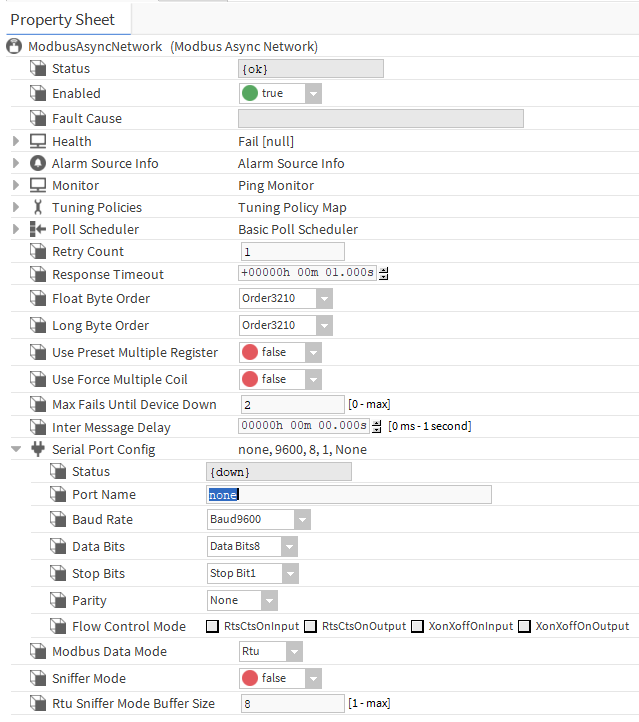
Solution
To set a proper serial communication port, set the Port Name slot to COM1, if a basic RS485 interface is used, or COM2, if an additional RS485 serial port is used (available only in the MAC36NL-RS series).
Communication parameters are not properly set for devices on the bus
A baud rate of the serial port set by default in the ModbusAsyncNetwork component is 9600 (the Baud Rate slot in the Serial Port Config section) and data transmission is by default configured to 8n1 (respectively, Data Bits, Parity, and Stop Bits slots in the Serial Port Config section). This configuration is rooted in default parameters presumed by Tridium for all devices Powered by Niagara.
In case of iC devices such as I/O modules, panels, etc., a default Modbus RTU configuration of communication is as follows:
-
baud rate
115200, -
data transmission
8n1.
In case of SfAR devices, a default Modbus RTU configuration of communication is as follows:
-
baud rate
19200, -
data transmission
8n1.
Default settings in different devices may vary by manufacturer and it cannot be taken for granted that one or any of these parameters will be configurable.
Solution
Verify the baud rate and transmission settings in all devices on the RS485 bus, which the MAC36NL serial port is connected to. All devices must have the same settings of these parameters.
In case there are various manufacturers' devices on the bus, which differ by parameters' configuration options, resulting in no way to standardize all parameters between devices on the bus, it is required to divide the RS485 bus to two. To divide the RS485 bus, it is necessary to provide another RS485 port, either by exchanging MAC36NL to MAC36NL-RS) or exchanging any I/O module without the Ethernet port to the one with the Ethernet port to create a Modbus TCP/IP to Modbus RTU gateway.
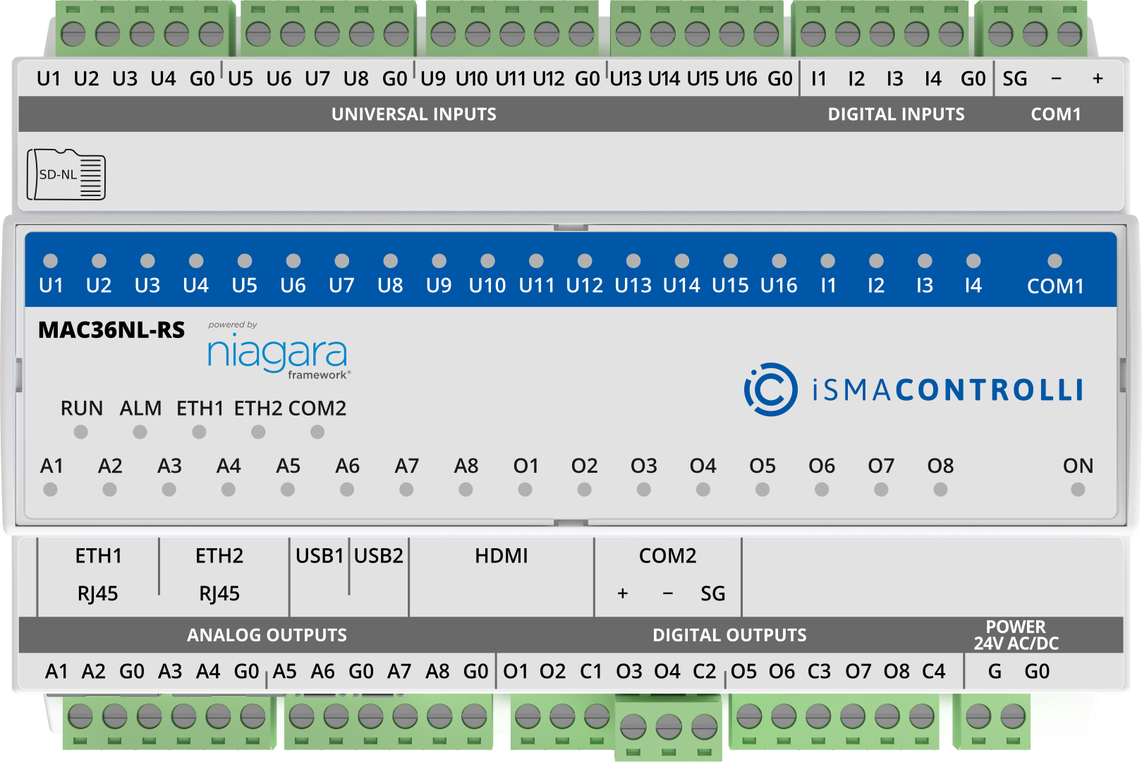
MAC36NL-RS - the COM2 RS485 port is not working
Sporadically, the COM2 extension in the MAC36NL does not work. Switching the Network component and the RS485 bus to COM1 results in the correct operation of the system.
Solution
-
Verify if the COM2 port is not busy by another RS485 driver (e.g., ModbusAsyncNetwork or BACnet MS/TP port).
-
The COM2 port may have been burnt as a result of a wrong connection or the extension is faulty by factory; either way it will not work correctly.
Attempt to ping the device's register which is a part of a larger variable
Some devices have a default pinging address set to a register which is a port of a bigger variable (e.g., of string type). In such a case, pinging this register will fail, because reading a single register of the bigger variable may be prevented by factory. The device will not respond to the ping or will respond with an error frame.
Solution
It is recommended to always set a default pinging address from the device’s register table.
No support for 0x03 or 0x04 functions of the Modbus RTU slave device
Not all devices on the market declared as compliant with Modbus standards are in fact fully functioning Modbus RTU devices. It is often the case that such devices only support one frame (compliant with the Modbus RTU standard), for example, saving values of all parameters at one time to a slave device using the 0x10 function. Such device will never be discovered by MAC36NL, because it cannot respond to one frame using the 0x03 (holding register) or 0x04 (input register) function and it is a necessary condition for the ping function in the ModbusAsyncDevice component. Without it, the slave device can never be discovered in the network - this refers to all Modbus RTU master devices Powered by Niagara.
Solution
For Modbus RTU communication with the MAC36NL controller, use devices which can respond with the 0x03 or 0x04 function to a query on a declared register address.
Wrong or no answer from the Modbus RTU slave device
Sporadically, a Modbus RTU slave device responds to a frame adding additional bytes. For example, for the below query:
01h 03h 27h 2Eh 00h 01h EEh B7h
a correct answering frame would look like this (the response depends on the current value in the 11 815 dec register):
01h 03h 02h 00h 17h F8h 4Ah
Unfortunately, the device responds with an additional byte, 74h:
01h 03h 02h 00h 17h F8h 4Ah 74h
Such frames are incorrect in Modbus RTU because the number of bytes in the response does not match the query. Also, normally, the last 2 bytes of a frame are a CRC-16 checksum, so MAC36NL reads 4Ah 74h as the checksum, whereas the actual checksum are bytes F8h 4Ah and 74h should never be included in the frame.
In the Internet, there are probably tools which can interpret such frames by reading only first 7 bytes and neglecting whatever is redundant, however, MAC36NL (or any other controller Powered by Niagara) verifies the slave device responses in detail and reports any inconsistencies.
The reason to adding a byte in a frame may be as follows:
-
internal manufacturer’s requirements,
-
interferences on the Modbus RTU bus,
-
too high baud rate,
-
too low capacity of the bus,
-
firmware error in the Modbus RTU slave device.
Solution
Here, the solution has to be determined by elimination:
-
Fulfilling internal requirements of the manufacturer - in this case, the instructions should be included in the device’s documentation. The most popular requirements refer to:
-
setting a minimal timeout (e.g., 2000 ms) - devices based on older or slower microcontrollers may run into a problem with a speed of processing Modbus frames, therefore, they may require setting higher value for the timeout. Please note that setting a higher timeout decreases the capacity of the bus;
-
setting an additional delay between frames - some manufacturers require an additional time between frames and normally it is 10 or 20 ms. Please note that setting an additional delay decreases the capacity of the bus.
-
-
Reducing interferences on the Modbus RTU bus:
-
interferences may result from a too close space between the high current cables and communication lines when laid parallel - a minimal spacing between cables should be at least 10 cm;
-
third wire (G0) is not connected - a third wire (G0) must always be connected in the MAC36NL controller, it allows to equalize reference potential between communication ports of all devices on the RS485 bus. Please note that the shield of the communication cable cannot be taken as the third wire;
-
wrong connection of a communication cable shield - a shield is used to pull all collected interferences to ground, therefore, it must be connected to grounding (not G0) only in one place, and for the other devices, it is required to maintain the shield continuity and its isolation with no connection to device terminals or grounding. Connecting the shield to ground in a few places results in flowing of equipotential currents between different points of grounding, which means introducing another interference on the bus.
-
interferences can be reduced by terminating the bus on its both ends and by turning on biasing on the first device. Please note that turning on more terminators on the bus (or placing them in wrong points) or turning on biasing on more than one devices may result in deterioration of the RS485 bus interferences;
-
also, too low quality bus cables may be a reason to communication problems - it is recommended to use shielded cables dedicated to the RS485 bus with an appropriate capacitance and internal impedance; additionally, in case of the MAC36NL controller, 3-wire cables are recommended.
-
-
Occasionally, devices can have firmware capabilities for high speed communication but their hardware may fall behind on stability communicating with high baud rates - in such a case, it is recommended to try communication with lower baud rates, however, it requires setting the same baud rate on all devices on the bus.
-
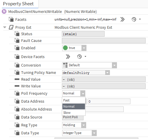
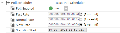
If the bus is set to a low baud rate (e.g., 9600) with a high number of devices on the bus, frequent polling, and a high number of points, some of the points (or even devices) may fall out of the RS485 bus’ capacity. It has to be verified and counted every time with a large bus with frequent polling of points. It is advised to decide which points do not have to be polled every 1000 ms and optimize polling frequency of points by setting their Poll Frequency slots to different values and by extending their
Fast Rate,Normal Rate, andSlow Ratepolling times in thePoll Schedulersection of theModbusAsyncNetworkcomponent.
-
In case the Modbus RTU device has a firmware error, verify if any firmware updates are available and upload it if it is.
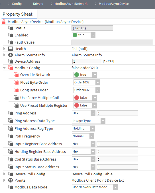
Read 32-bit value is not compliant with the value in the remote device
By default, 32-bit values stored in 2 Modbus registers are read by Niagara in the 3210 byte order, where the digits represent numbers of bytes.
Sometimes, devices (including iSMA CONTROLLI devices) have a different registers' order.
Solution
In such a case, it is recommended to change the byte order for the network from Order3210 to Order1032:
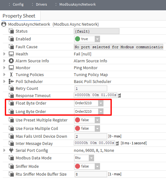
This change will be applied to all devices on the bus.
If the change is meant to be applied only to selected devices, go to their ModbusAsyncDevice components, expand the ModbusConfig section, and set the OverrideNetwork slot to true; then change the byte order: