Local I/O
The multiprotocol I/O modules are equipped with local inputs and outputs (universal inputs, digital inputs, analog outputs, digital outputs, and triac outputs), and their quantities differ between the modules types, according to the table:
|
Module Type |
UI |
DI |
AO |
DO |
TO |
|---|---|---|---|---|---|
|
4I4O-H |
|
4 |
|
4 |
|
|
4I4O-H-IP |
|
4 |
|
4 |
|
|
4O-H |
|
|
|
4 (NC/NO-8A) |
|
|
4O-H-IP |
|
|
|
4 (NC/NO-8A) |
|
|
4U4A-H |
4 |
|
4 |
|
|
|
4U4A-H-IP |
4 |
|
4 |
|
|
|
4U4O-H |
4 |
|
|
4 |
|
|
4U4O-H-IP |
4 |
|
|
4 |
|
|
8I |
|
8 |
|
|
|
|
8I-IP |
|
8 |
|
|
|
|
8U |
8 |
|
|
|
|
|
8U-IP |
8 |
|
|
|
|
|
4TO-H |
|
|
|
|
4 |
|
4TO-H-IP |
|
|
|
|
4 |
|
MIX18 |
5 |
5 |
4 |
4 |
|
|
MIX18-IP |
5 |
5 |
4 |
4 |
|
|
MIX38 |
8 |
12 |
6 |
12 |
|
|
MIX38-IP |
8 |
12 |
6 |
12 |
|
|
12O-H |
|
|
|
12 |
|
|
12O-H-IP |
|
|
|
12 |
|
|
24I |
|
24 |
|
|
|
|
24I-IP |
|
24 |
|
|
|
Inputs and outputs in multiprotocol I/O modules
Universal Inputs
Universal inputs support four types of input signals:
-
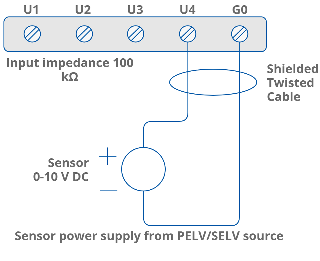
voltage (0-10 V DC, input impedance 100 kΩ);
-
current (0-20 mA);
-
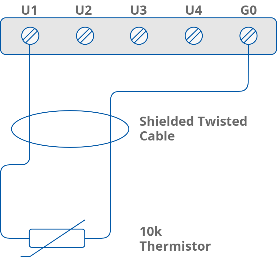
resistance and temperature measurement (10k thermistor, a full list of supported temperature sensors is available here: List of Supported Temperature Sensors);
-
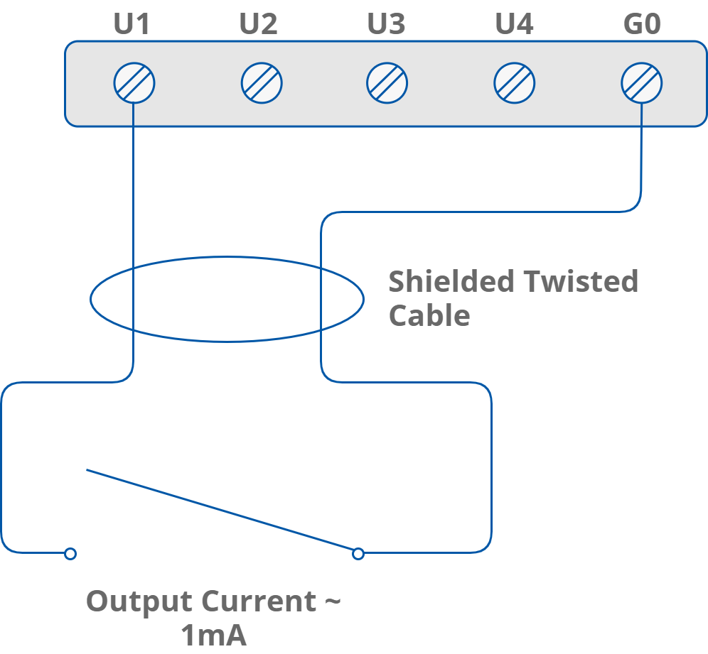
dry contact (output current 1 mA).
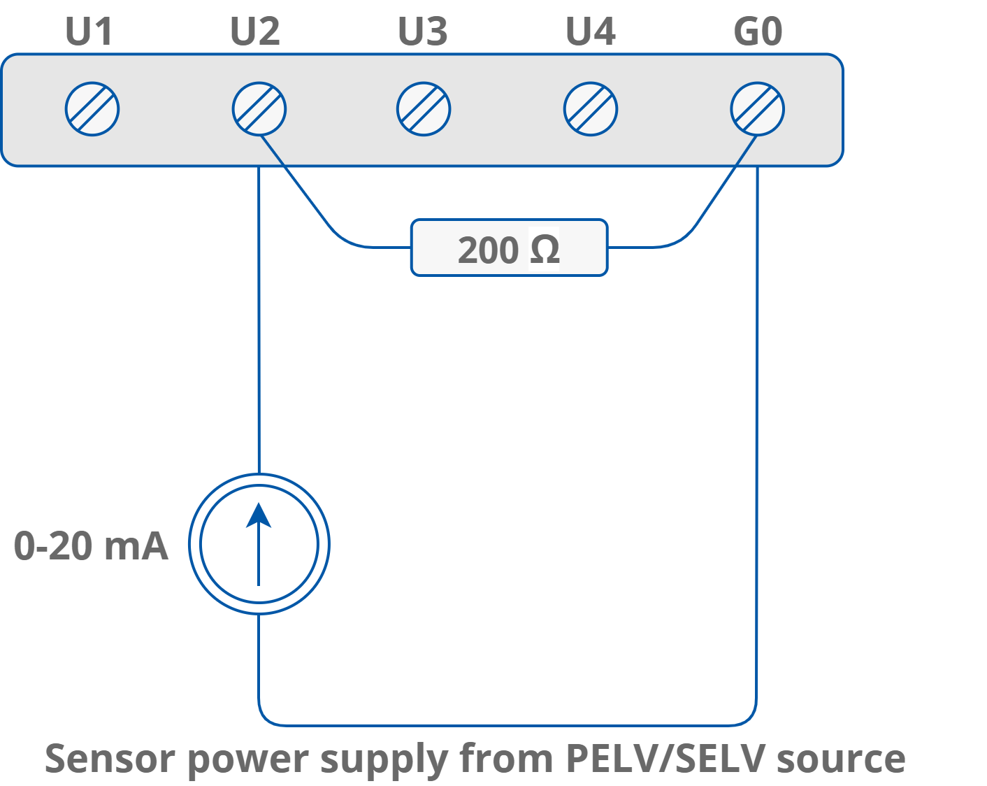
Current measurement is realized by voltage measurement and 200 Ω resistance. According to Ohm’s law, the current is directly proportional to the voltage, and the resistance is the constant of proportionality. (I = U / R). According to the Ohm’s law equation, for 20 mA current with 200 Ω resistance the output voltage is 4 V. It means that the 4 V voltage measured on the universal input corresponds to 20 mA current. The result is expressed in millivolts.
Universal Input Voltage Connection
Universal Input Current Connection
Universal Input Resistance Connection
Universal Input Dry Contact Connection
Digital Inputs
Digital inputs operate as standard dry contact inputs and, additionally, as high speed pulse counters up to 100 Hz.
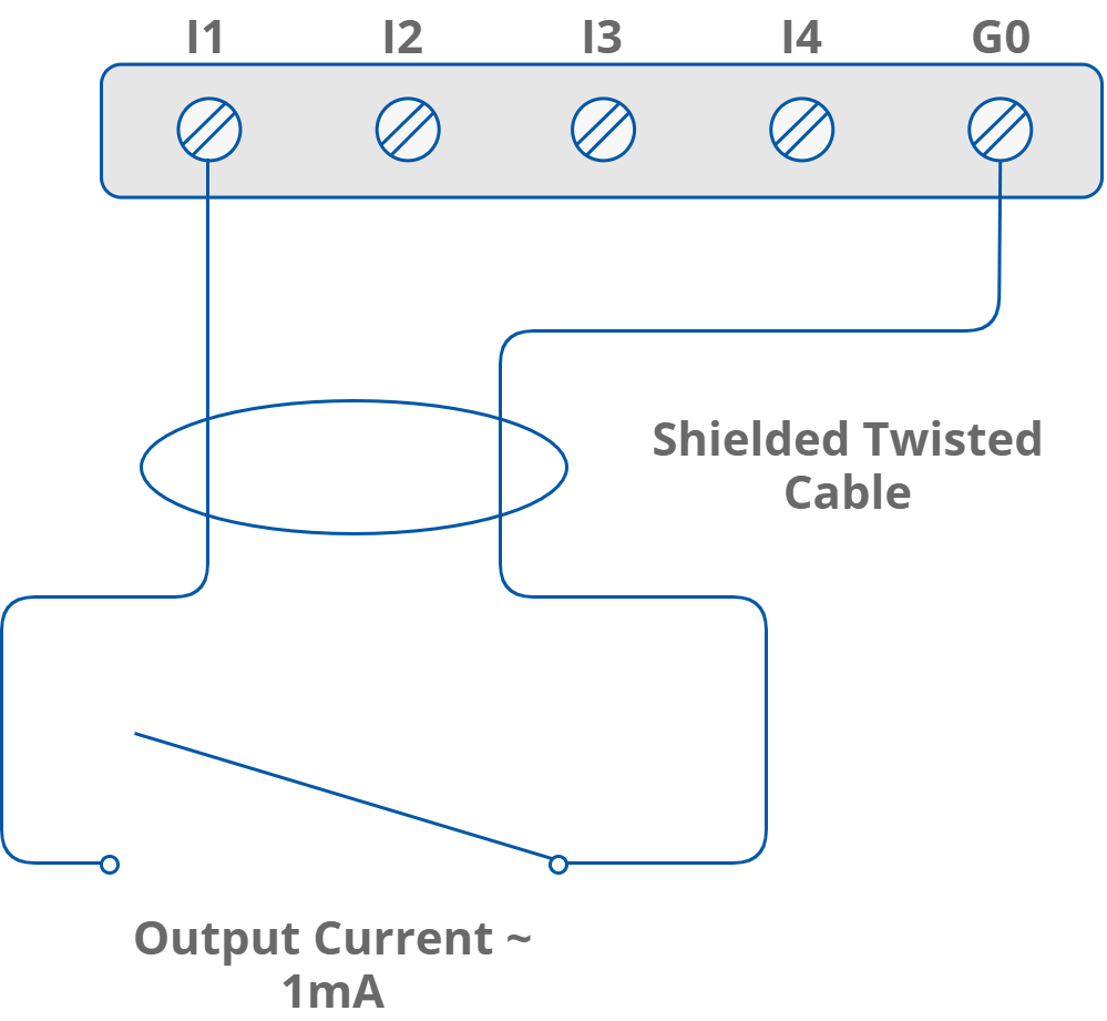
Digital Input Counter
A digital input can work as a counter of dry contact pulses up to 100 Hz. The connection is identical as in case of the dry contact input.
Analog Outputs
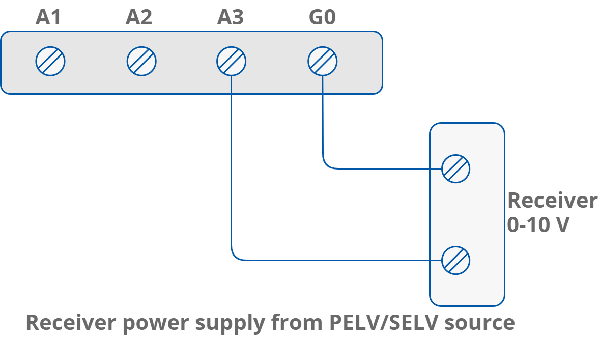
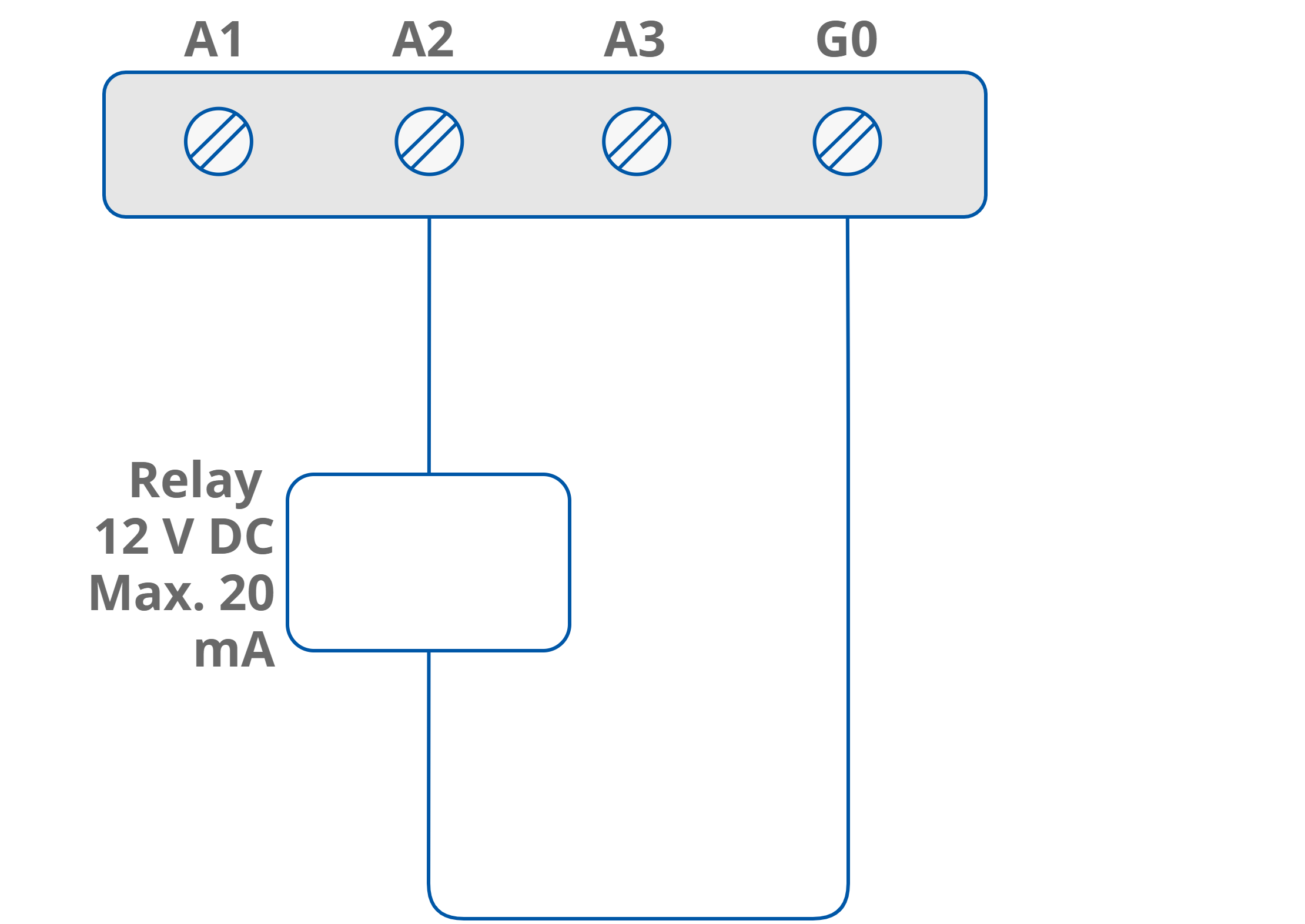
Analog outputs provide a 0-10 V DC output with maximum load up to 20 mA. They support three types of output signals:
-
voltage (0-10 V DC) with maximum load up to 20 mA;
-
digital;
-
Pulse Width Modulation (PWM) 0,01 Hz, 0,1 Hz, 1 Hz, 10 Hz, 100 Hz.
Analog Output Voltage Connection
Analog Output Relay Connection
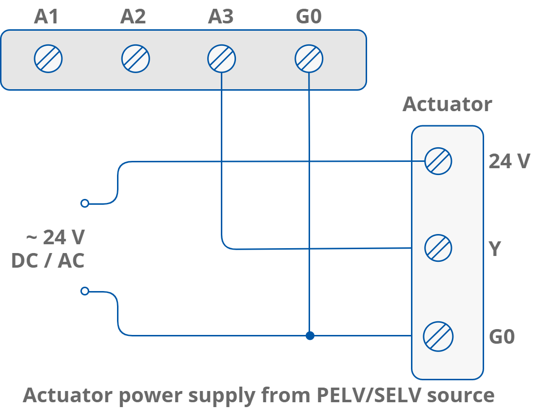
Analog Output Actuator Connection
Digital Outputs
Digital outputs operate as relay outputs with maximum loads of:
|
|
UL compliant ratings |
Maximum ratings |
|
|---|---|---|---|
|
Digital outputs (relays) |
Resistive load (AC1) |
3 A at 24 V AC 3 A at 30 V DC |
3 A at 230 V AC 3 A at 30 V DC |
|
Inductive load (AC3) |
8 VA at 24 V AC 30 W at 30 V DC |
75 VA at 230 V AC 30 W at 30 V DC |
|
|
4O-H and 4O-H-IP |
Resistive load (AC1) |
8 A at 230 V AC 8 A at 30 V DC |
8 A at 230 V AC 8 A at 30 V DC |
|
Inductive load (AC3) |
37 VA at 230 V AC 90 W at 30 V DC |
360 VA at 230 V AC 90 W at 30 V DC |
|
Resistive and inductive loads for digital outputs
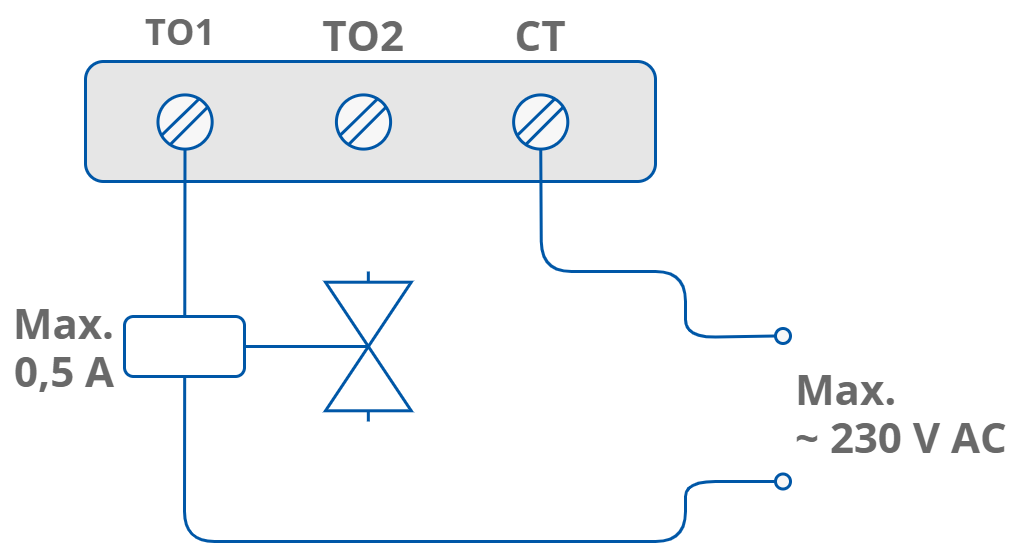
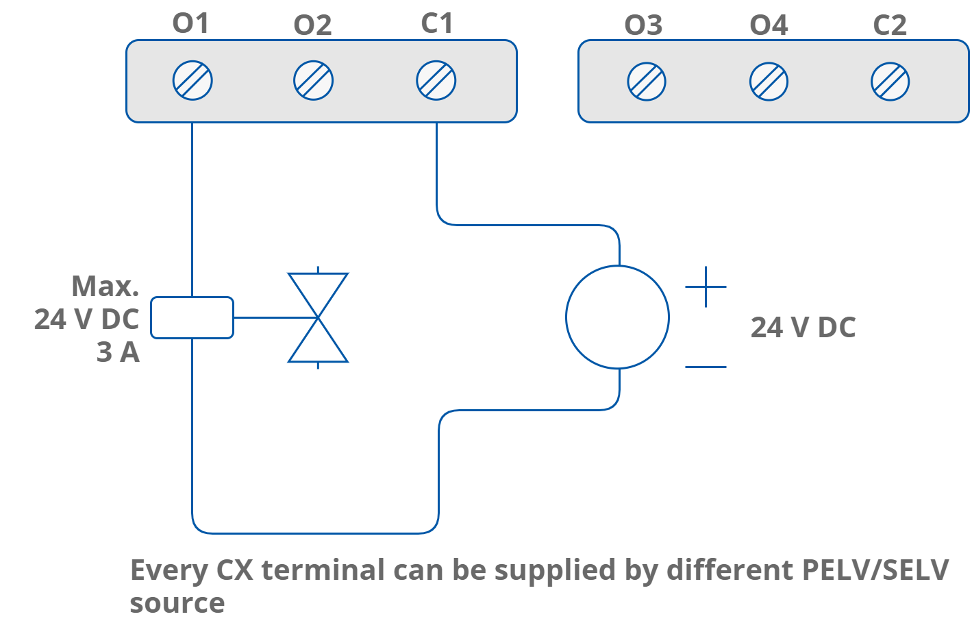
Digital Output Solenoid Valve Connection
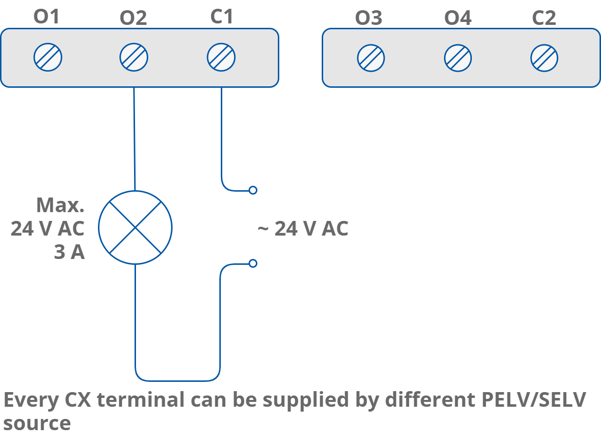
Digital Output Resistive Load Connection
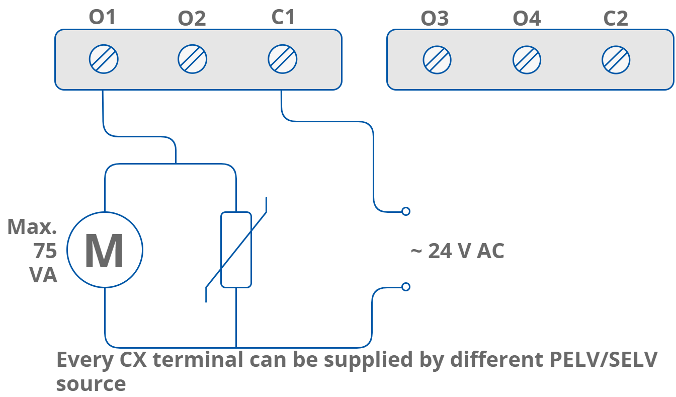
Digital Output Inductive Load Connection
Triac Outputs
Triac outputs work as typical binary outputs or in Pulse Width Modulation (PWM) mode: 0,01 Hz, 0,1 Hz, 1 Hz, 10 Hz.