This document shows the principle of heating/cooling operation in analogue and digital mode for fan coil units.
iSMA-B-FCU heating control method is essentially simple. The fan coil unit is designed to maintain a constant temperature in the room in which I am located, while in winter it can heat the air in the room acting as a heater. In iSMA-B-FCU, use the available outputs appropriately, and then set the temperature of interest, so that the built-in default application will set the valves to obtain the desired temperature. Depending on the control mode, the user has 1 of 3 device outputs at his disposal:
-
A1 Analog output (only analog control mode),
-
TO1 Triac output (digital and analog control modes),
-
O4 Relay output (digital control mode only).
An example of the connection of heating devices is presented below:
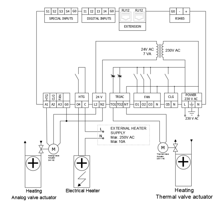
Picture 1. Scheme of connection of heating devices.
1. Digital heating mode
In this mode, the output signal works like a typical PWM, i.e. it has a high and a low state. There are two outputs TO1 and O4, A1 is turned off by default. The default application controls the filling of the PWM signal in such a way as to obtain the temperature setpoint 'Setpoint'. The O4 output is on by default, but it is recommended only if nothing is connected. The O4 output can be disabled with the network variable 'HTG_Relays_Enable'.
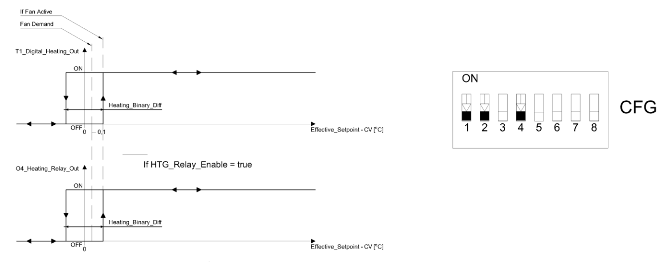
Picture 2. Graph showing the principle of operation of the digital mode and configuration of CFG 'DIP switch'.
2. Analog heating mode
In this mode, the output value is calculated in the range of 0 - 100% through the PI controller included in the default iSMA-B-FCU application. Two outputs A1 and TO1 are available, the output O4 is off by default.
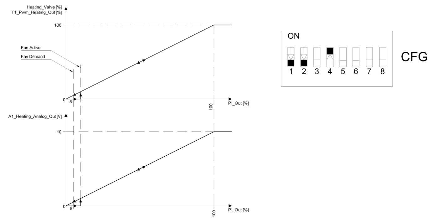
Picture 3. Graph showing the principle of operation of the analog mode and configuration of the CFG 'DIP switch'.
In the case of the digital mode, the fans are turned on together with the high state of the PWM signal, and in the case of the analog mode, when the PI controller output is equal to or higher than 5%.
Cooling works on the same principle as heating a fan coil is designed to maintain a constant temperature in the room in which I am located, while in summer it can cool the air in the room by providing air conditioning. In iSMA-B-FCU, use the available outputs properly, and then set the temperature of interest to us, so that the built-in default application will set the valves to obtain the desired temperature. Depending on the control mode, the user can choose from 1 of 3 device outputs:
-
A2 - in 4-pipe mode analog output (only analog control mode),
-
A1 - in 2-pipe mode analog output (only analog control mode),
-
TO2 - in 4-pipe mode with Triac output (digital and analog control modes),
-
TO1 - in 2-pipe mode with Triac output (digital and analog control modes),
-
Relay output O5 (digital control mode only).
An example of the connection of cooling devices is presented below:
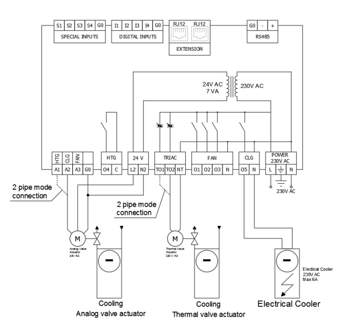
Picture 4. Diagram of connection of cooling devices.
3. Digital cooling mode
In this mode, the output signal works like a typical PWM, i.e. it has a high and a low state. There are two outputs TO2 and O5, A2 is turned off by default. The default application controls the filling of the PWM signal in such a way as to obtain the temperature setpoint 'Setpoint'. The O5 output is on by default, but it is recommended only if nothing is connected. The O4 output can be disabled with the network variable 'CLG_Relays_Enable'.
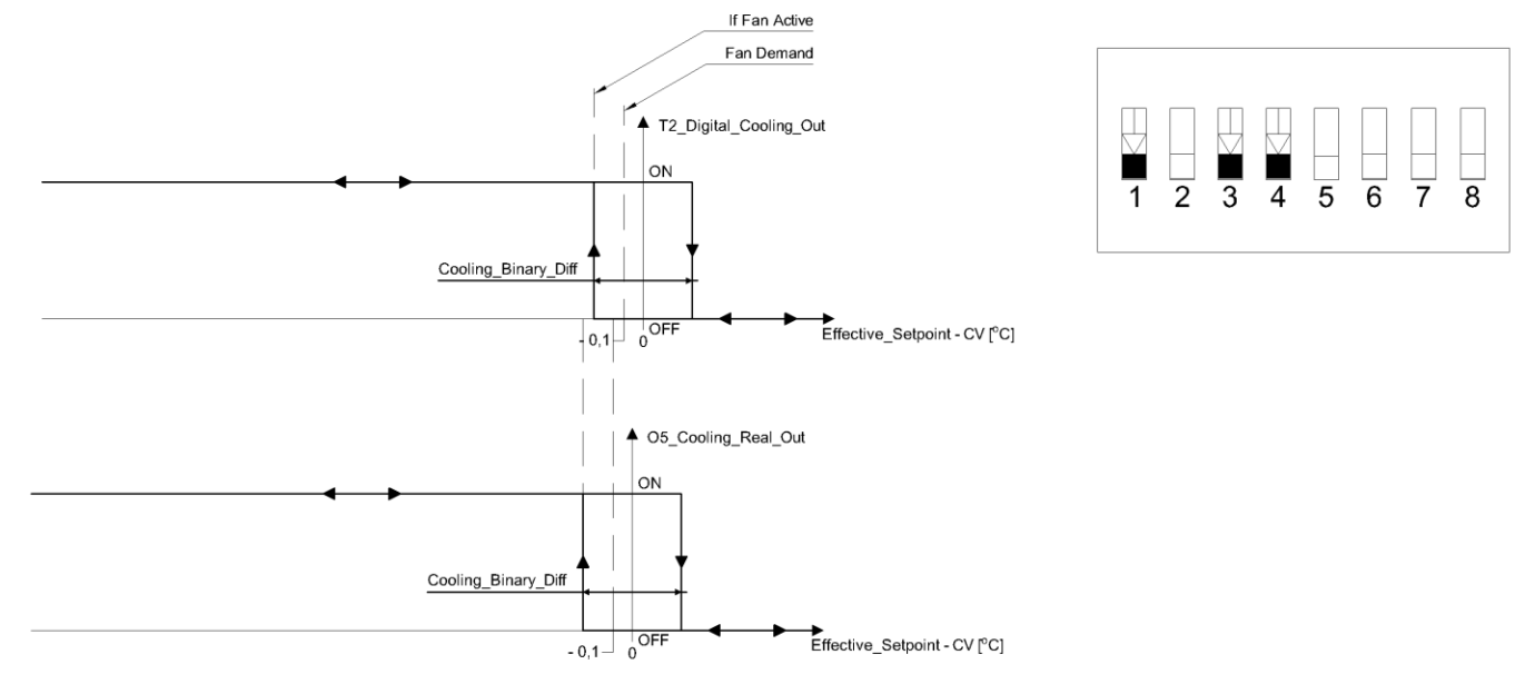
Picture 5. Graph showing the principle of operation of the digital mode and configuration of CFG 'DIP switch'.
4. Analog cooling mode
In this mode, the output value is calculated in the range of 0 - 100% through the PI controller included in the default iSMA-B-FCU application. Two outputs A2 and TO2 are available, the CLG output is turned off by default.
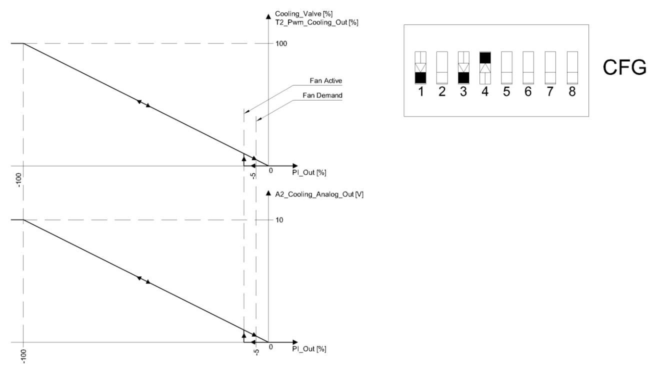
Picture 6. Graph showing the principle of operation of the analog mode and configuration of the CFG DIP switch'.
In the case of the digital mode, the fans are turned on together with the high state of the PWM signal, and in the case of the analog mode, when the PI controller output is equal to or higher than 5%.
Overall, the heating/cooling mode in iSMA-B-FCU is enabled by default, and the user can change its mode using 'DIP switch' number 4.
-
CFG number 4 'ON' - analog mode
-
CFG number 4 'OFF' - digital mode
5. Analog heating/cooling mode
In this mode, the algorithm is controlled by a PI controller that calculates the output value
in the range from -100% to 100%. The range from -100% to 0 is for cooling control, and the range from 0 to
100% is used to control the heating. In order to the algorithm does not start heating and cooling too quickly, the value of 'Valves_dead_band' can be adjusted. It describes the temperature deviation
from a set point where the PI controller does not activate heating/cooling.

Picture 7. Graph of the principle of operation of the variable 'Valves_dead_band'.
6. Digital heating/cooling mode
In this mode, the output signal works like a typical PWM, i.e. it has a high and a low state. Please note that the outputs O4 and O5 can only operate in digital mode, so if the user wants to use digital mode, these outputs should be turned off using network variables.
O4: 'HTG_Relays_Enable',
O5: 'CLG_Relays_Enable'.
