The following article describes how the manual control of digital and analog outputs works on the MINI-H and MAX-H modules.
1. Manual control of digital outputs.
MINI series modules: iSMA-B-4U4O-H, iSMA-B-4I4O-H, iSMA-B-4O-H and iSMA-B-4TO-H, and MAX series module: iSMA-B-12O-H, both in RS and IP versions, have built-in switches for manual operation of the outputs. In the event of a communication failure, service works, etc., the user has the option of manually switching on or off the digital outputs. The module signals the manual operation mode through the output diode, eg O1, O2, etc. In case of switching on the manual mode, irrespective of the output status, the output diode lights up with a flashing light. The user has the option to check if manual mode is enabled in the BMS using both Modbus and BACnet.
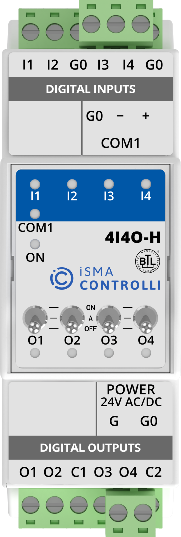
Picture 1. iSMA-B-4I4O-H device with switches to manual mode.
To activate the output, move the manual mode switch to the upper position, the lower position turns the output off, the middle position returns to the automatic mode. If the manual mode is on, it is not possible to remotely change the output state.
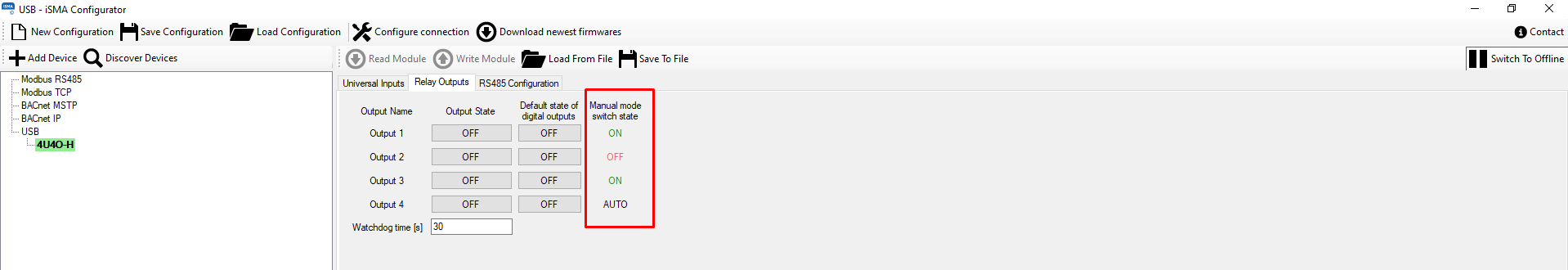
Picture 2. Status of outputs O1, O2, O3 in manual mode in iSMA Configurator.
Note: The status of the manual mode of the digital or Triac outputs is monitored by the Modbus register with the address 30015 and the BACnet objects of the Multistate Value type with the addresses 23-26.
2. Manual control of analog outputs.
iSMA-B-4U4A-H modules, both in RS and IP versions, have built-in switches for manual operation of the outputs. In the event of a communication failure, service work, etc., the user has the option of manually activating the analog outputs. The module signals the manual operation mode through the output diode, eg A1, A2, etc. In case of switching on the manual mode, irrespective of the output status, the output diode lights up with a flashing light. The user has the option to check if manual mode is enabled in the BMS using both Modbus and BACnet.
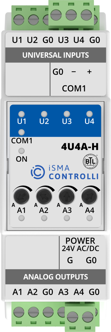
Picture 3. iSMA-B-4I4O-H device with potentiometers controlling manual mode.
To switch the output on, turn the manual mode potentiometer clockwise to the desired position. The current status of the output can be connected using e.g. iSMA Configurator. If the manual mode is on, it is not possible to remotely change the output state. The return to the automatic mode is made by moving the potentiometer to the extreme left position.
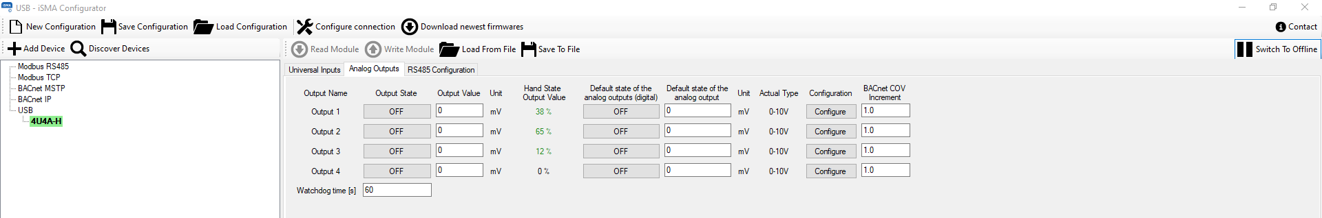
Picture 4. Status of A1, A2, A3 outputs in manual mode in iSMA Configurator.
Note: The status of the manual mode of the analog outputs is monitored by Modbus registers with addresses 30125-30128 and BACnet objects of the Analog Value type with addresses 22-25.