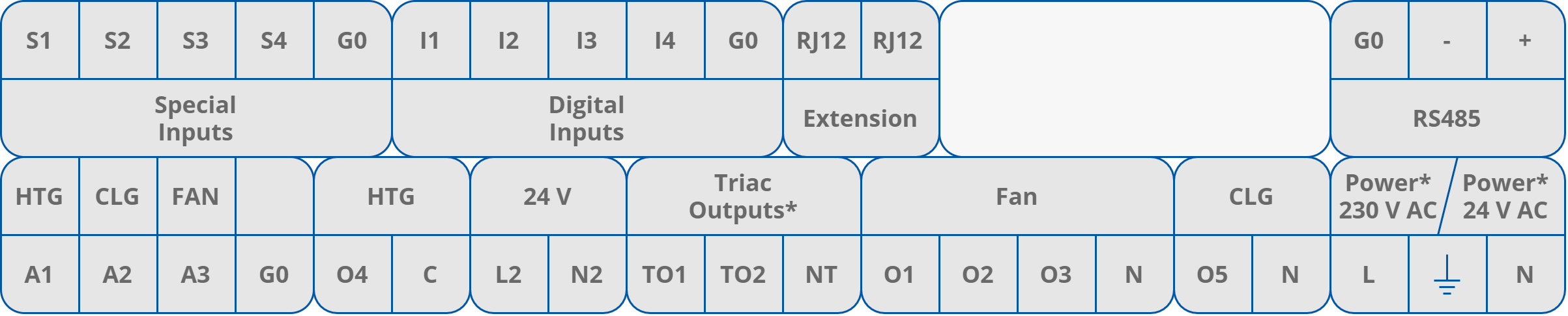
Connections Overview
Connection Examples
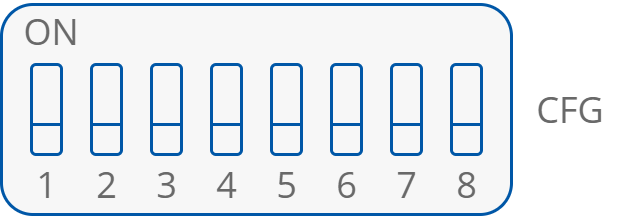
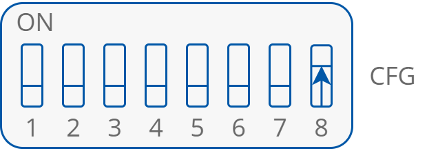
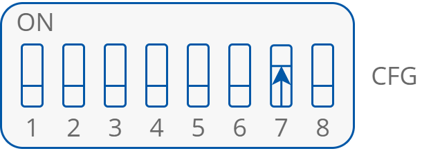
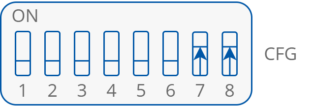
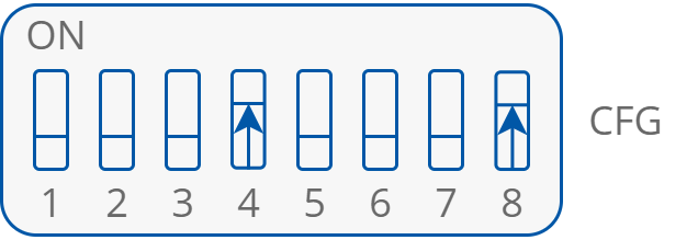
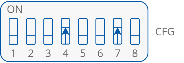
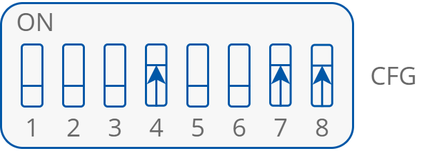
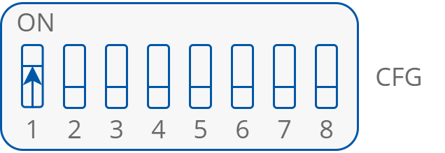
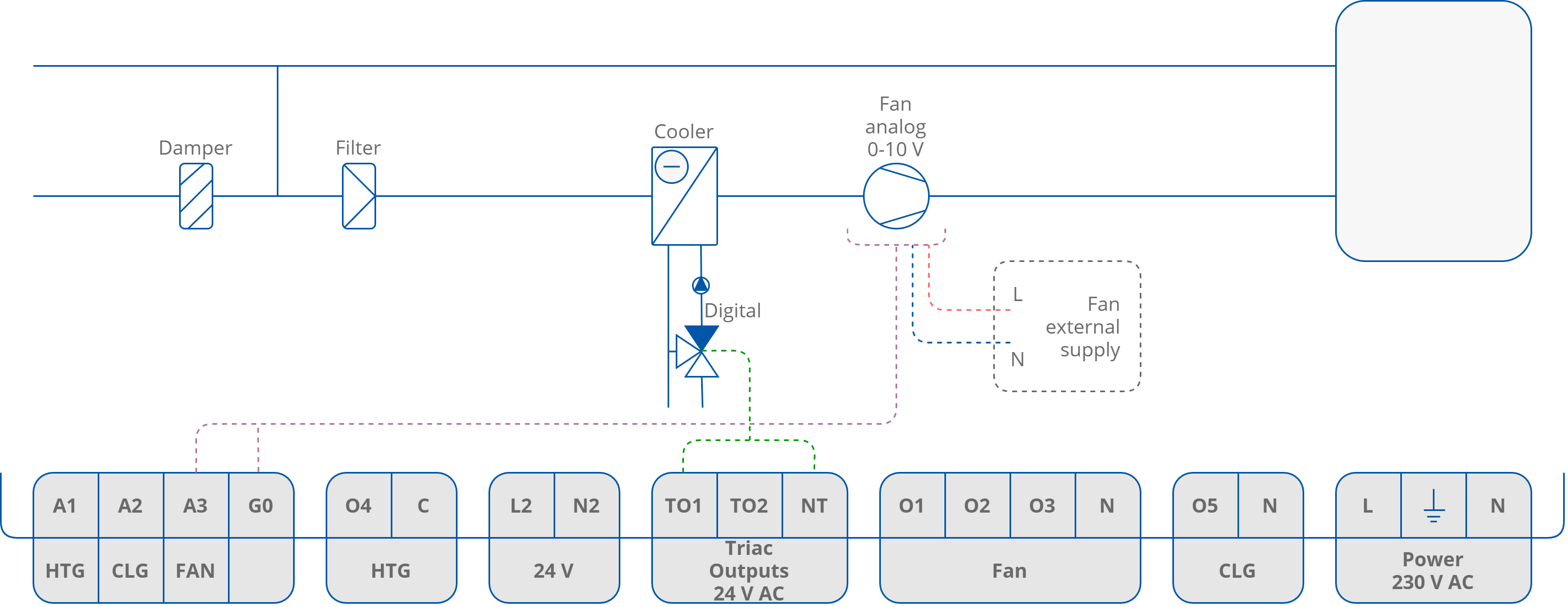
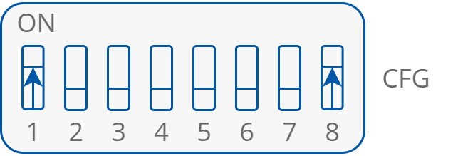
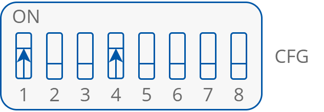
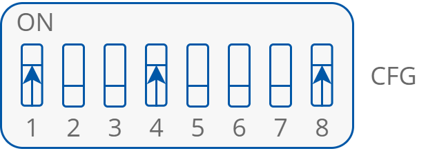
The examples below do not include selection of the temperature control value source. Connecting the temperature control value source is described in Step 7 of this manual. In examples, DIP switch sections 5 and 6 are set to OFF.
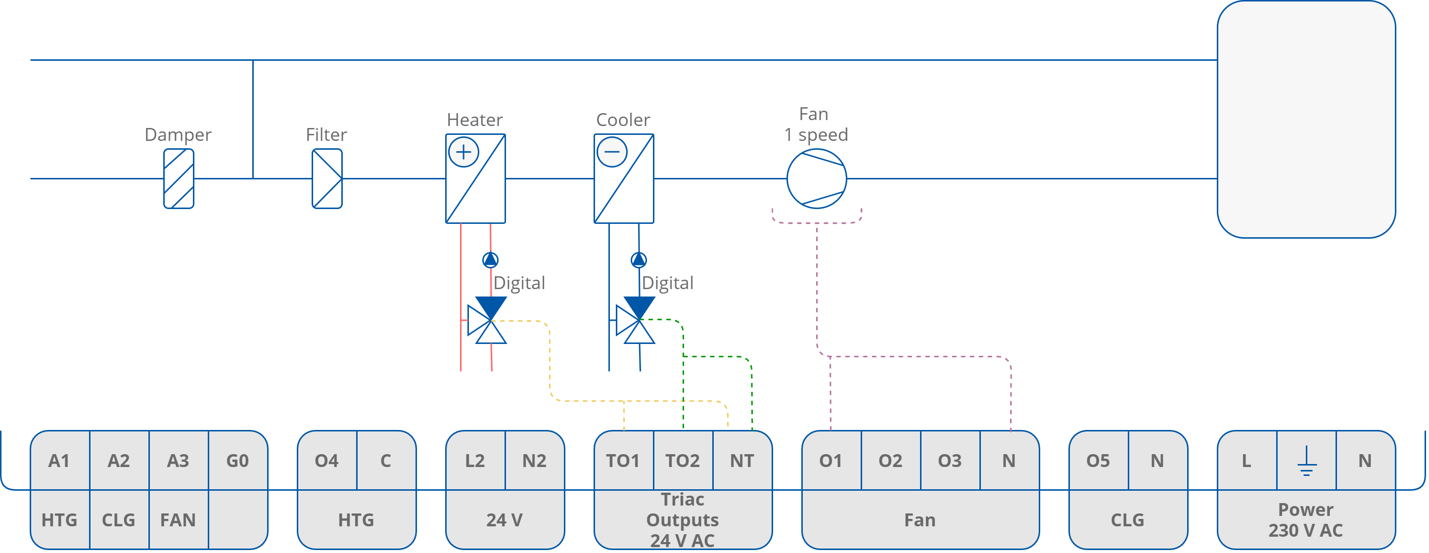
The 24 V power source for heater and cooler actuators can be taken from L2/N2 connectors.
If 2nd stages of heating or cooling is used, check Step 6 for connection information.
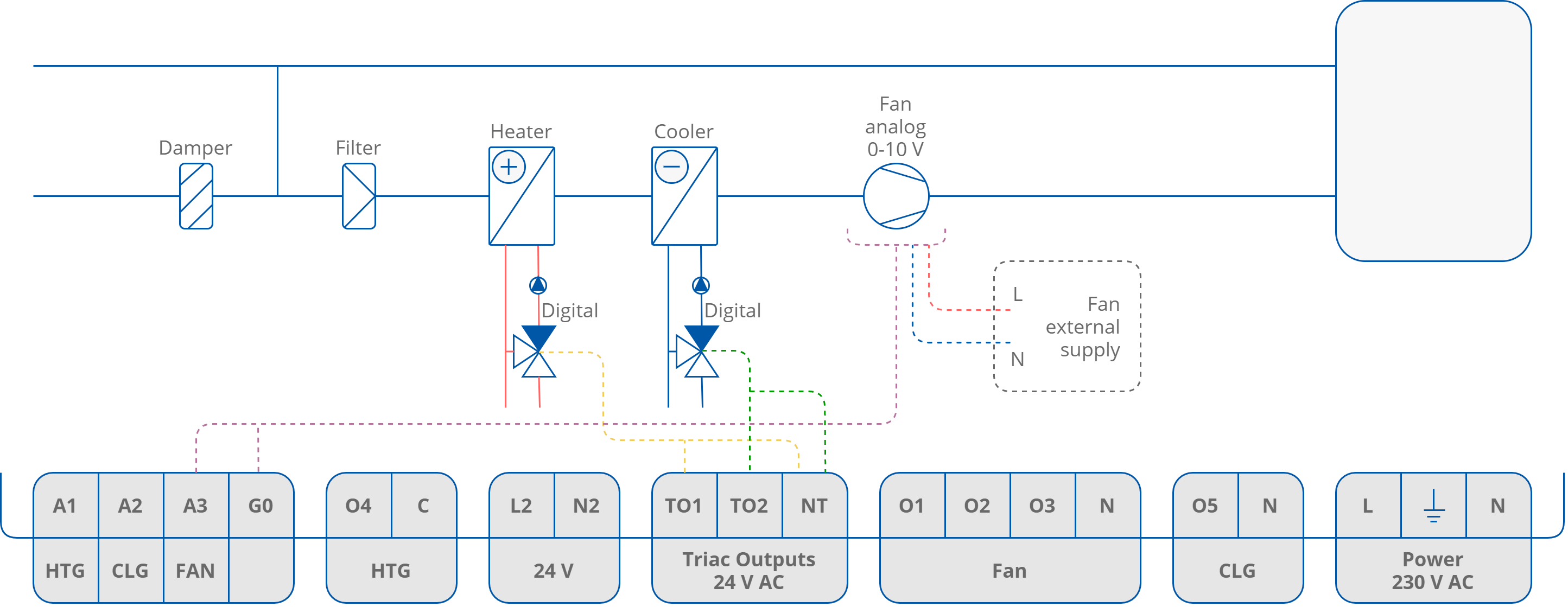
4-pipe Installation with 1-stage Digital Controlled Heating and Cooling and Analog Controlled Fan
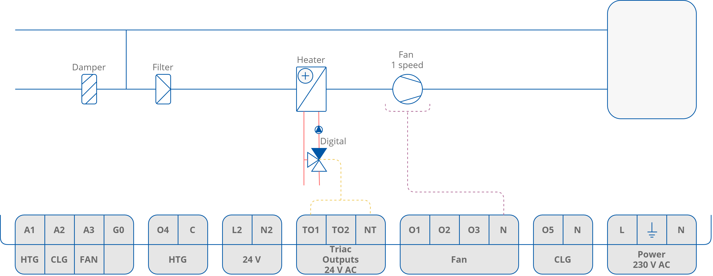
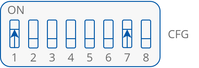
4-pipe Installation with 1-stage Digital Controlled Heating and Cooling and 1-speed Fan
4-pipe Installation with 1-stage Digital Controlled Heating and Cooling and 2-speed Fan

4-pipe Installation with 1-stage Digital Controlled Heating and Cooling and 3-speed Fan

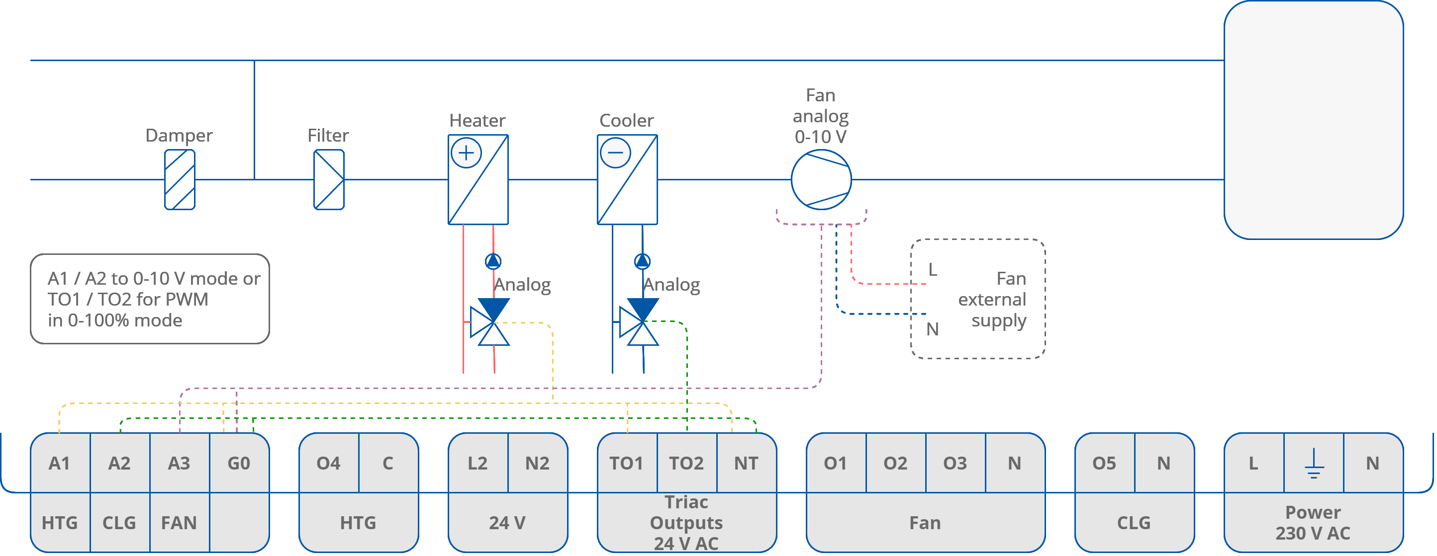
4-pipe Installation with 1-stage Analog Controlled Heating and Cooling and Analog Controlled Fan
4-pipe Installation with 1-stage Analog Controlled Heating and Cooling and 1-speed Fan

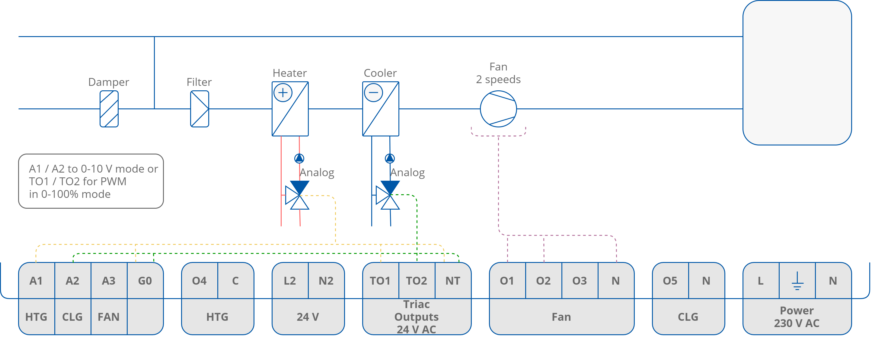
4-pipe Installation with 1-stage Analog Controlled Heating and Cooling and 2-speed Fan
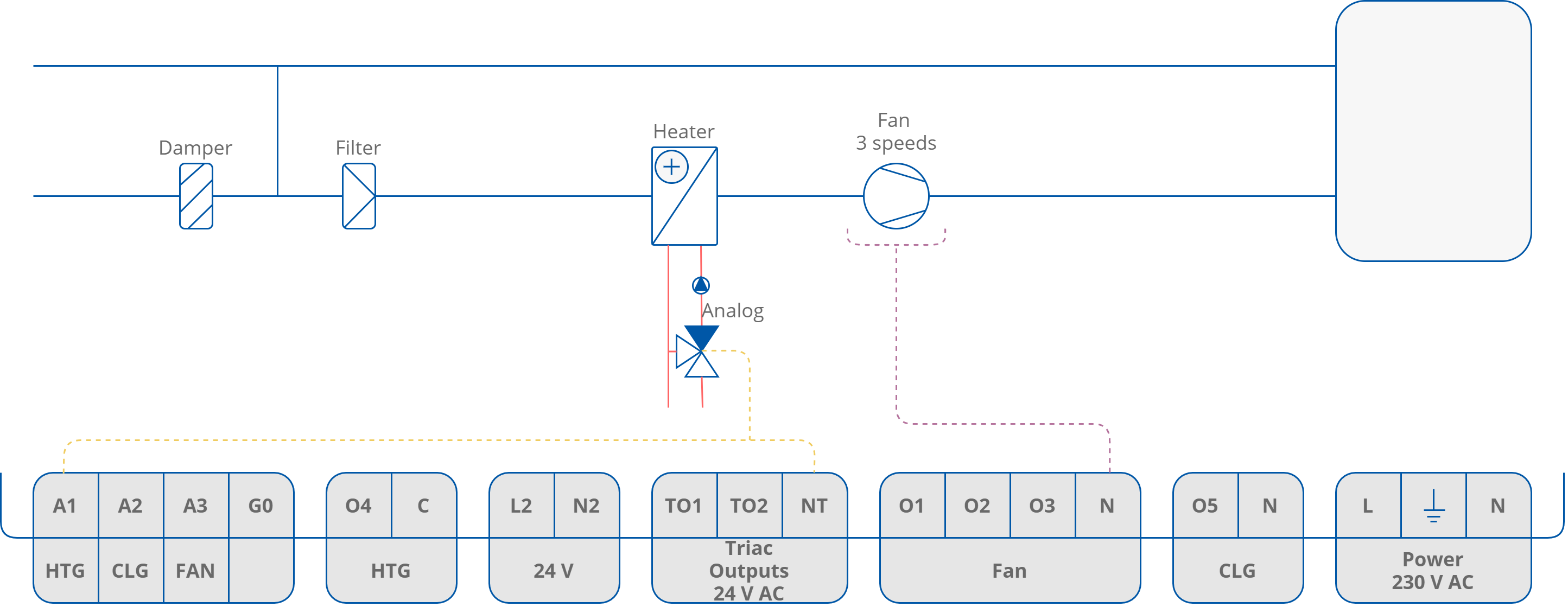
4-pipe Installation with 1-stage Analog Controlled Heating and Cooling and 3-speed Fan

2-pipe Installation with 1-stage Digital Controlled Cooling and Analog Controlled Fan
2-pipe Installation with 1-stage Digital Controlled Heating and 1-speed Fan
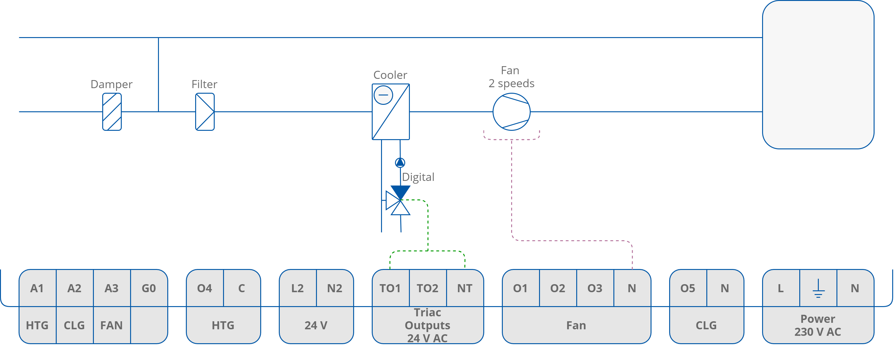
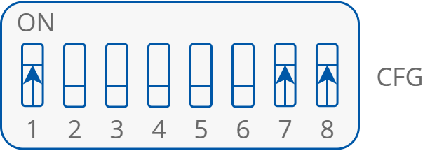
2-pipe Installation with 1-stage Digital Controlled Cooling and 2-speed Fan
2-pipe Installation with 1-stage Digital Controlled Heating and 3-speed Fan

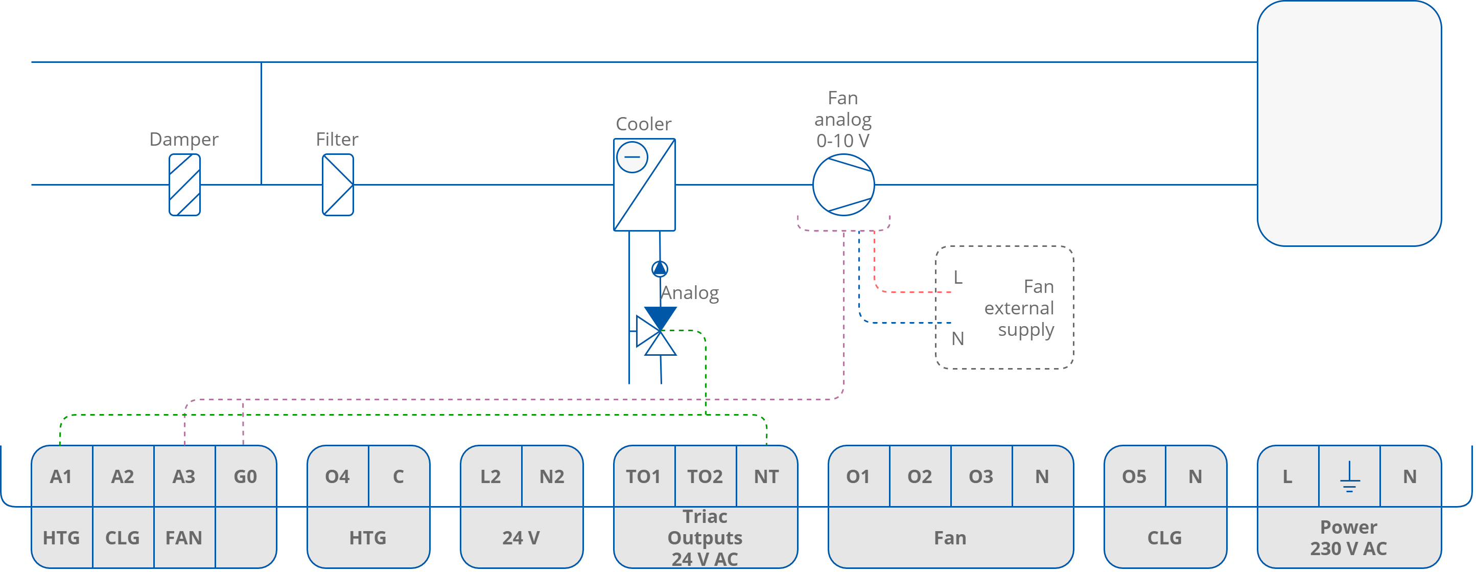
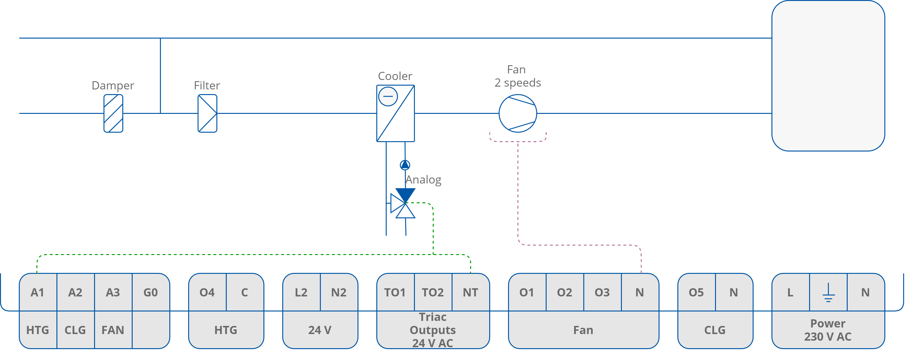
2-pipe Installation with 1 Stage Analog Controlled Cooling and Analog Controlled Fan
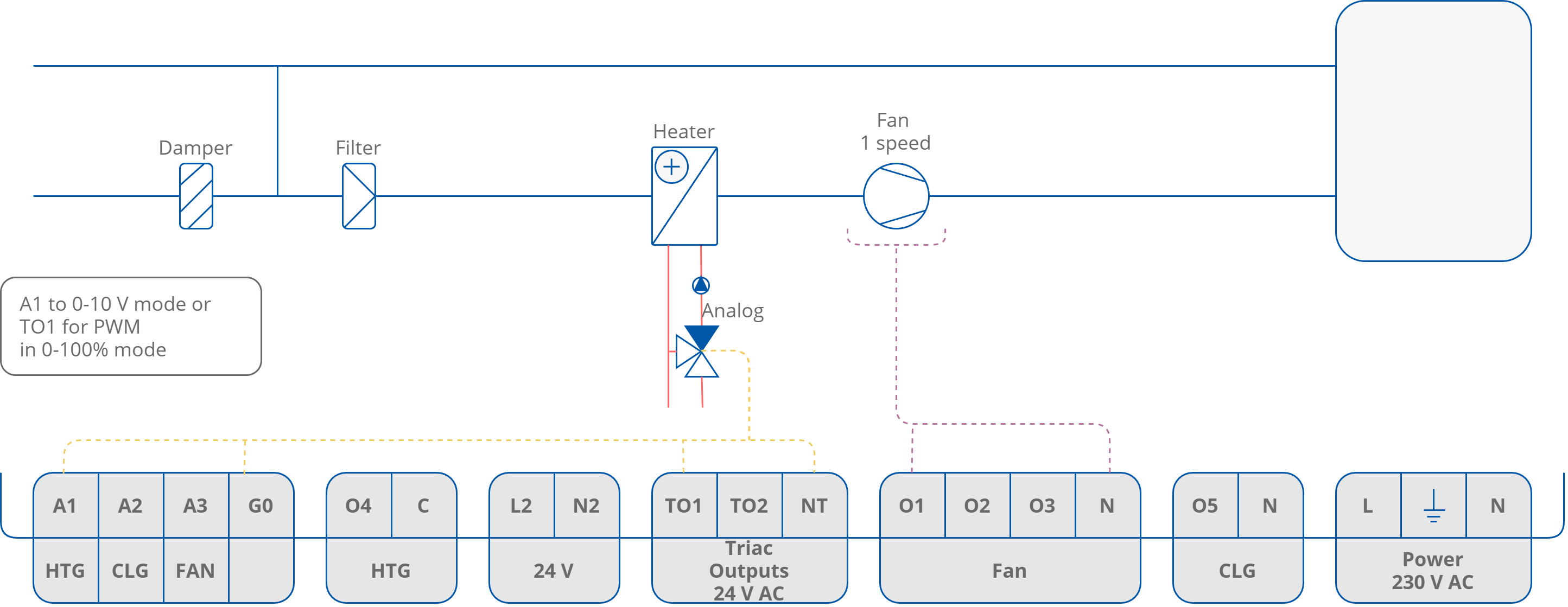
2-pipe Installation with 1-stage Analog Controlled Heating and 1-speed Fan

2-pipe Installation with 1-stage Analog Controlled Cooling and 2-speed Fan
2-pipe Installation with 1-stage Analog Controlled Heating and 3-speed Fan