LLC mode configuration
The light level control is a mechanism that allows for automatic (yet, adjustable) control of light level in two lighting zones, using 2 light sensors. The algorithm keeps light intensity on the setpoint level in a room automatically, based on the PID algorithm, using light sensors with standardized output connected to the iSMA-B-2D controller. The value of present light intensity is transmitted to the controller, which recognizes a need to increase or decrease DALI ballasts control level to keep desired level of light intensity if surrounding conditions change.
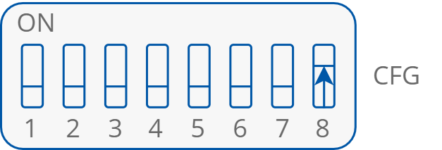
The LLC mode requires setting the 8th section on the CFG DIP switch to on.
Sensors
Light sensors are required to be used for the LLC function to operate properly. There are seven parameters to be set for light sensors (configurable in the iSMA Configurator software):
-
LUX_SENSOR_TYPE_1, LUX_SENSOR_TYPE_2: define types of lux sensors used;
-
LUX_MIN_SENSOR_1, LUX_MAX_SENSOR_1: define minimum and maximum lux values for zone 1;
-
LUX_MIN_SENSOR_2, LUX_MAX_SENSOR_2: define minimum and maximum lux values for zone 2;
-
LUX_SENSOR_ENABLE: enables each sensor with specific bit state.
Switches
Switches connected to the I1 and I2 inputs control DALI1 and DALI2 buses ballasts. A short press pulse causes switching on and off the ballasts. A long press causes changing the setpoint of the specific zone, which in final effect results in smoothly controlling the light intensity.
.png?cb=d0892361d27f669932c6a1d7d730c9d5)
Switches and sensors connected to digital inputs
In case the LLC mode is set to operate in 1 zone, the I4 input can be used for switching the light, using the light 2 relay output. Each pulse on I4 (pushing the monostable button) switches on or off the light 2 output.
Note: The light 2 output is switched off automatically if DALI1 and DALI2 buses are switched off with a switch connected to I1, however, it happens only if the CFG DIP switch in section 2 (I1 Control mode) is set to on. In order to switch the light 2 output back on, the switch connected to I4 has to be switched.
.png?cb=7f35753ac8fba3e38518eeef93fe45f6)
The light 2 control switch connected to I4
Zones
The light level control mechanism allows to control up to two lighting zones. The LLC_ZONE_COUNT parameter defines if one or two zones are controlled with the LLC:
-
1 zone only, using 1 light level sensor with a possibility to separate DALI ballasts for:
-
first sub-zone, which is directly controlled with the light setpoint value (DALI 1 bus), using the sensor value from the S1 input as reference;
-
second sub-zone, which is controlled with the light setpoint value with offset (DALI 2 bus), still using the sensor value from the S1 input as reference;
-
Note: The offset value is set in the LLC_OFFSET parameter, accessible in the iSMA Configurator, LLC tab.
-
2 separated zones, where each zone has a separated control loop, and 2 light level sensors are used, connected to the S1 input (loop for the DALI 1 bus) and to S2 input (loop for the DALI 2 bus).
Note: If the LLC mode is set to 1 zone, the I4 input can be used for switching the light using the light 2 relay output. Each pulse on the I4 input (pushing the monostable button) switches on or off the light 2 output.
Dimming
The LLC mode provides a feature of automatic dimming if there is no one present in a room. In case the presence detector informs the room is empty, the LLC setpoint is automatically decreased to save energy consumption: if the PIR sensor does not detect presence for the time specified in the LLC_PIR_1_DIMM_TIME parameter, the setpoint is internally changed to the percent value LLC_PIR_1_DIMM_LEVEL of the basic value from the LLC_SETPOINT_ZONE_1.
Also, the LLC mode allows to switch off the light if the presence sensor detects no movement after the time specified for dimming. In case the dimming time expires, the second timer starts to count down the time to switch off the light completely. This time is set in the SI1_DELAY_OFF_TIME parameter. This feature works accordingly in 2 zones mode, using the LLC_PIR_2_DIMM_TIME and LLC_PIR_2_DIMM_LEVEL parameters with reference to the LLC_SETPOINT_ZONE_2 and SI2_DELAY_OFF_TIME parameters.
Adjusting Dimming PID Algorithm
Dimming is controlled with the internal PID algorithm. It is adjusted to fit most internal spaces conditions, however, it can be individually set using the following parameters:
-
For zone 1: LLC_KP_ZONE_1, LLC_KI_ZONE_1, and LLC_KD_ZONE_1;
-
For zone 2: LLC_KP_ZONE_2, LLC_KI_ZONE_2, and LLC_KD_ZONE_2.
The parameters define proportional, internal, and derivative gains of the loop algorithm, which controls dimming. They are accessible in the iSMA Configurator, LLC tab.