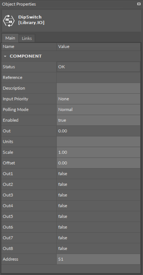
The DipSwitch component is an I/O point (network point class) component, which allows to read the bit states of DIP switches installed in the front panel of the RAC18-IP device. There are three DIP switches installed in the front panel: one 6-position (S1) and two 8-position (S2, S3). The DipSwitch component values are updated in every execution cycle of the Local IO component.
The DipSwitch component slots
Slots
The DipSwitch component has the following slots:
-
Status: indicates the current status of the component; if the component works properly, its status is OK. The component becomes Disabled, once the Enabled slot is in false;
-
Available information: Disabled, OK;
-
-
Reference: a special slot allowing to connect network point class components with Data Point class components. It allows to transfer the Out slot value along with the component's status.
By default, once the Reference link is created from the network point to the Data Point it sets the input priority to 16, which later can be changed manually.
-
Description: an additional detailed information about a service that may be freely described by the user; the description may contain individual coding, defined in the user's system documentation, or any other information the user finds applicable.
-
InputPriority: allows to select the input number in the Data Point, which the value from the network point class component's output is sent to; by default, the priority is none and sets to 16 after linking with a Data Point;
-
Available settings: none, 1-16.
-
Note: The Reference link from the network point to the Data Point cannot be changed to a 17th, default, priority.
-
Polling Mode: allows to set the frequency of sending polling requests for the point's value—by default, the polling mode is set to normal;
-
Available settings: fast, normal, slow;
-
-
Enabled: change of the slot's value enables or disables the component—if the component becomes disabled, it stops to read values from the physical input; by default, the component is enabled.
-
Available settings: true (enabled), false (disabled).
-
Note: If the Enabled slot is in false (meaning the component is disabled), the Status slot becomes Disabled.
-
Out: displays the binary sum of bits (bit no. 1 = 2^0, + 2^1 for bit no. 2, etc.);
-
Units: defines a unit of the Out slot value; no unit is used here by default;
-
Scale: sets a fixed scaling factor for output linearization; the Out value is calculated according to the linear function formula (y=ax+b), and the Scale slot set the a value of the formula;
-
Offset: sets a fixed offset value to the output value; the Out value is calculated according to the linear function formula (y=ax+b), and the Offset slot set the b value of the formula;
-
Out1-Out8: shows the binary value of the respective bit on the addressed DIP switch;
-
Available states: true or false;
-
Worth to Notice
In case of the 6-position DIP switch, the Out7 and Out8 slots are permanently false. The 6th switch in the true state restores factory settings in the controller.
-
Address: allows setting the address of the DIP switch, which bits are read in slots Out1-Out8;
-
Available settings: S1 (6-position DIP switch), S2 (8-position DIP switch), S3 (8-position DIP switch).
-
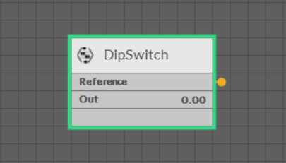
The DipSwitch component linked