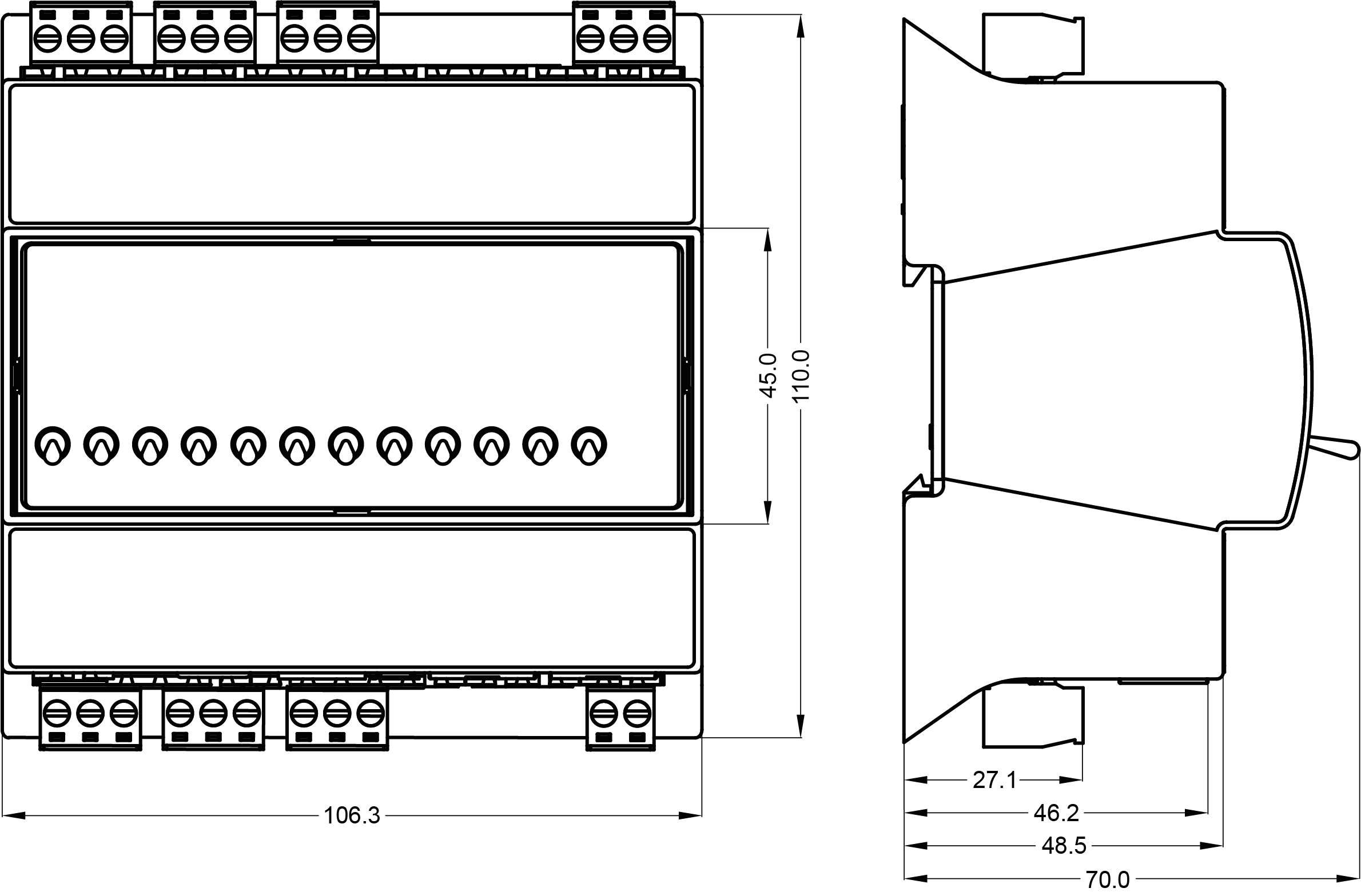
Dimensions
MINI Series (Without Hand Switches)
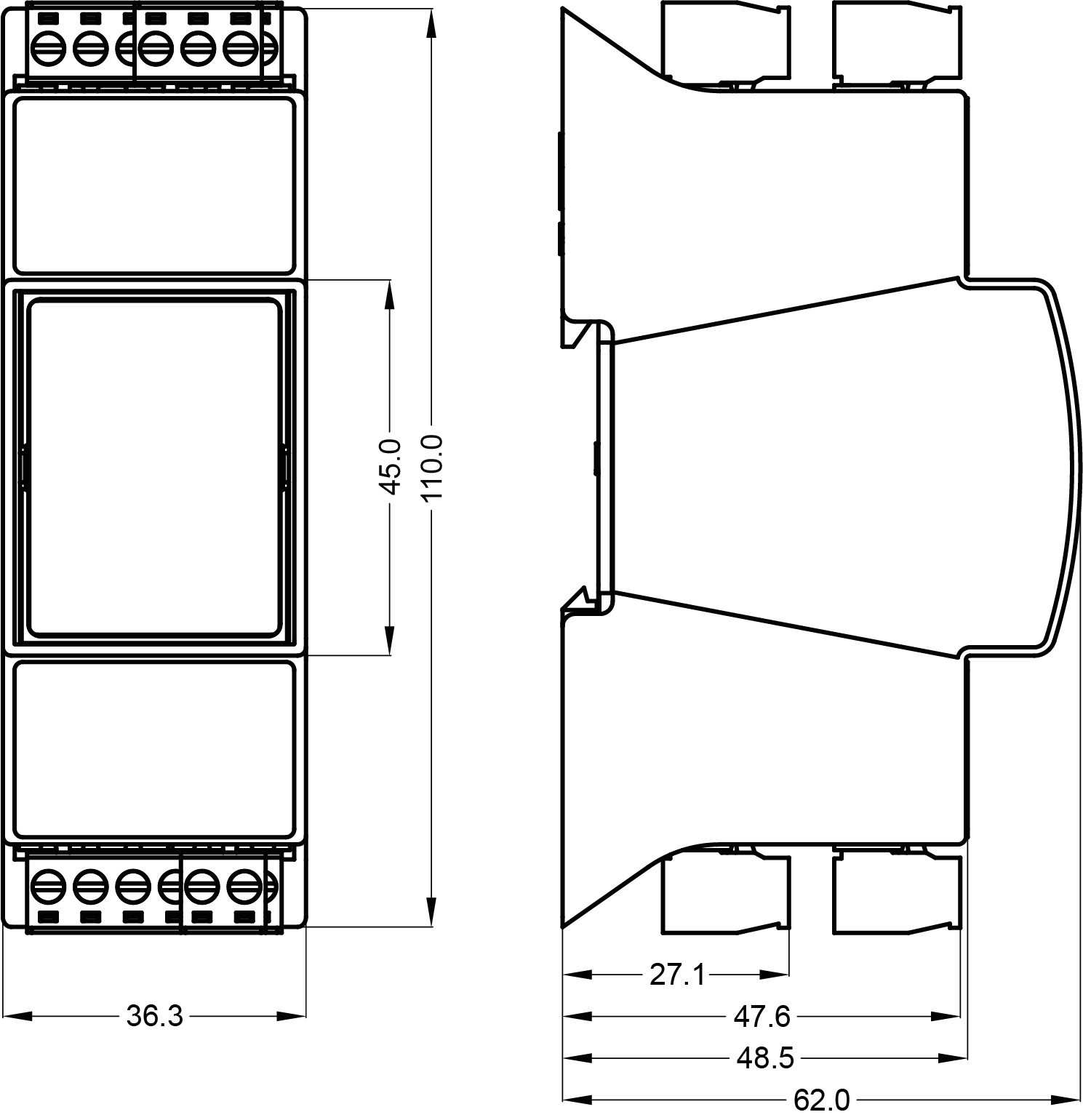
MINI Series (With Hand Switches)

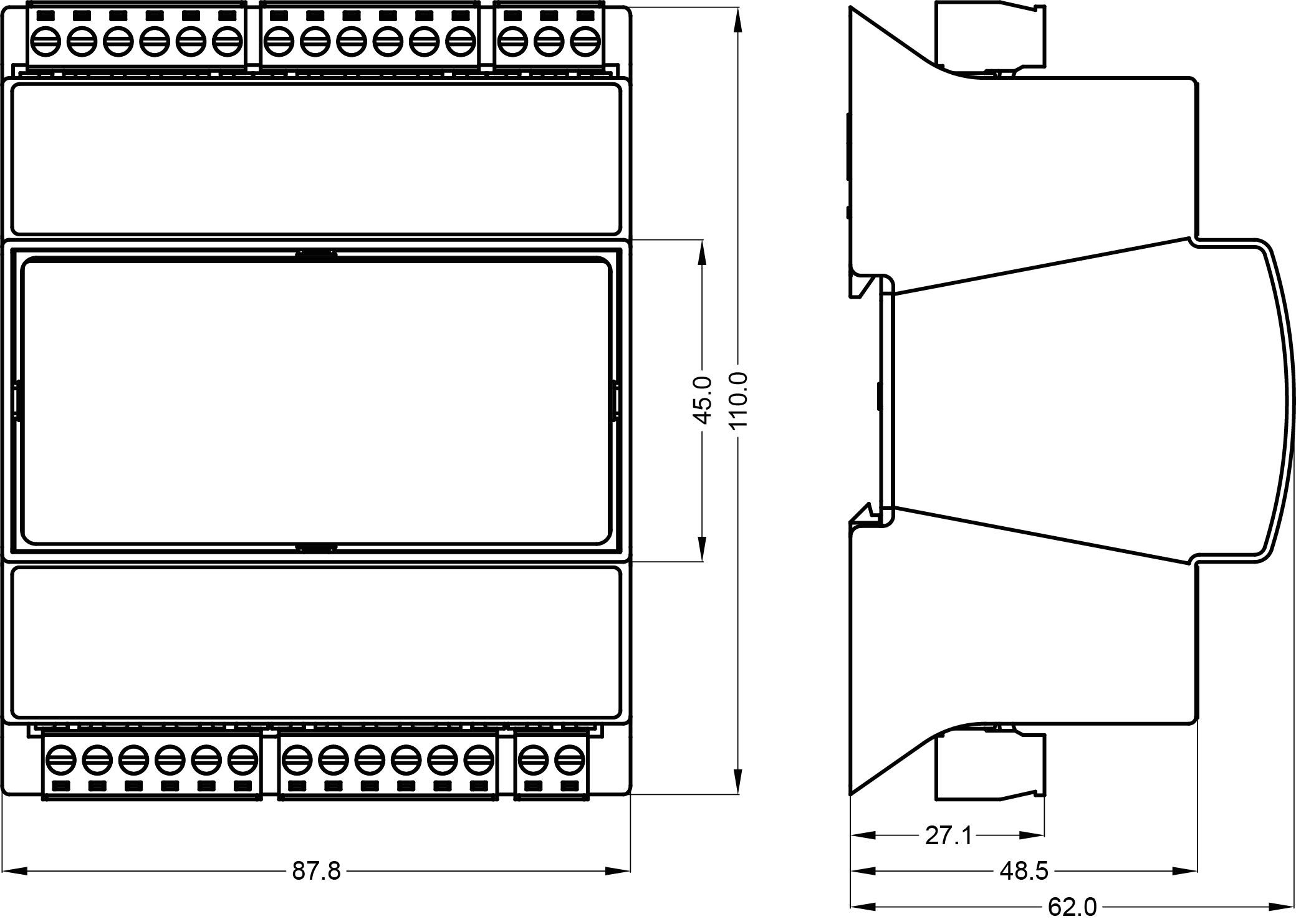
MIX18 Series
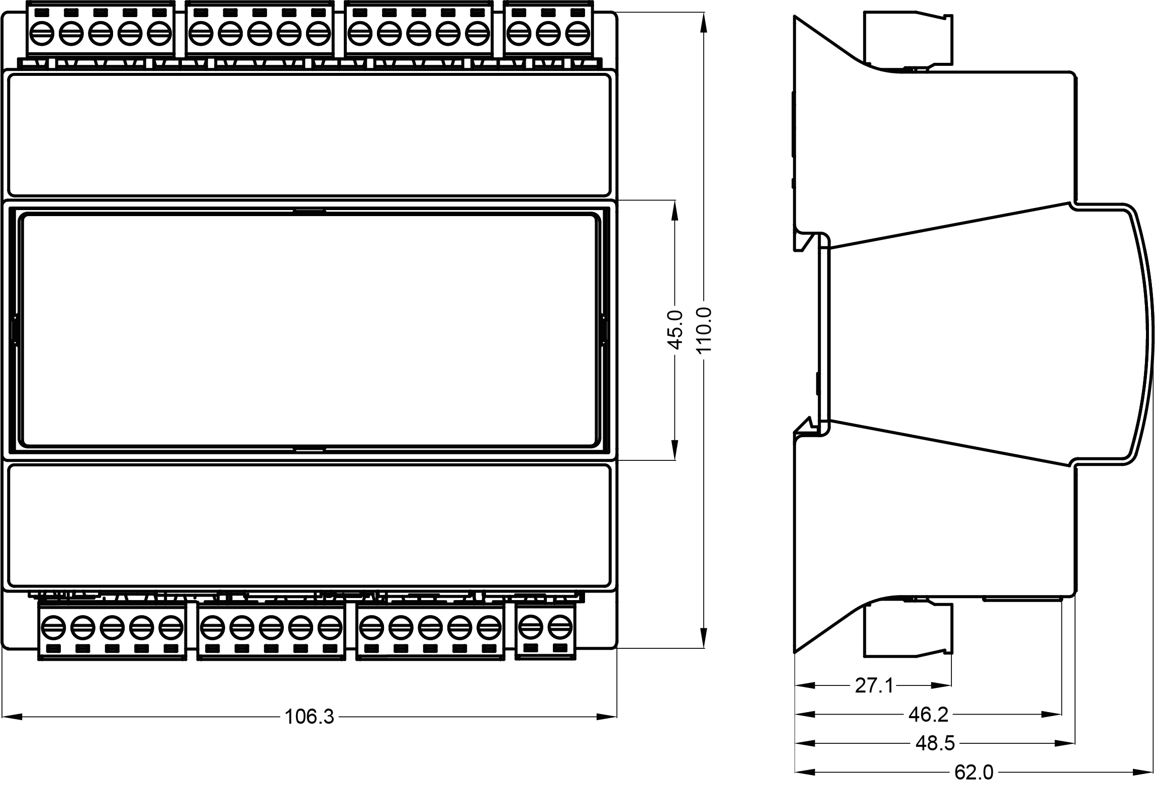
MIX38 Series
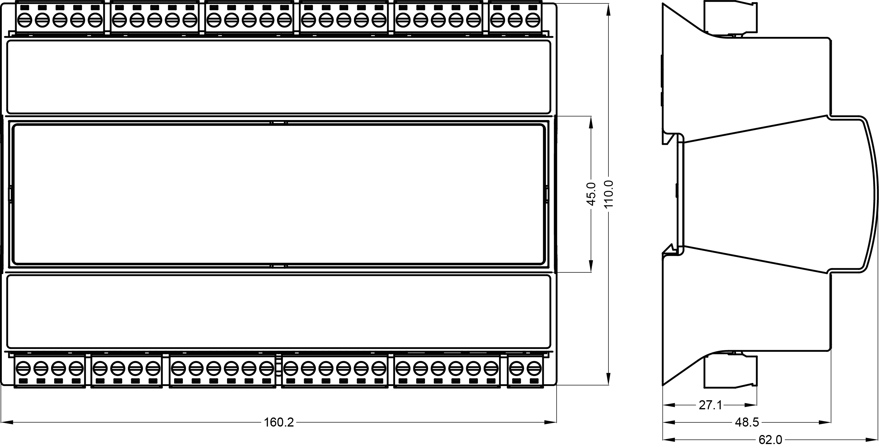
MAX Series (Without Hand Switches)
MAX Series (With Hand Switches)
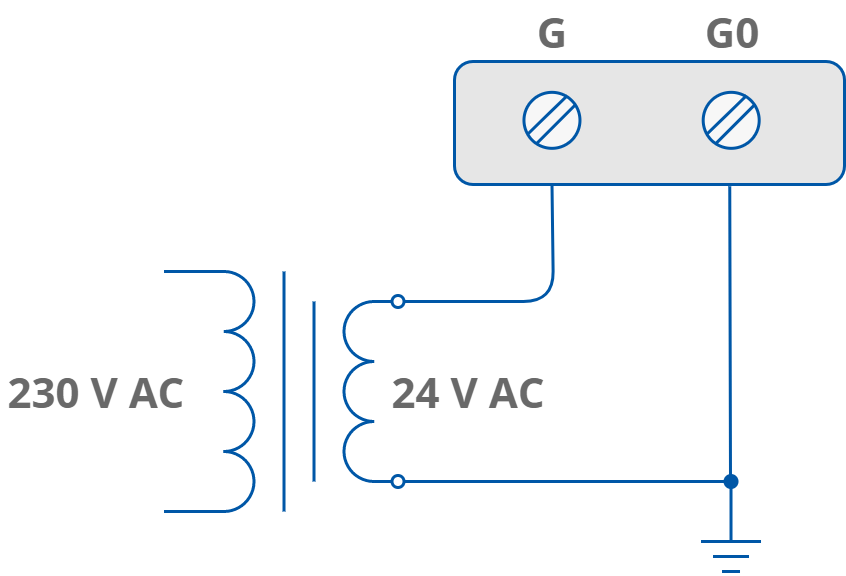
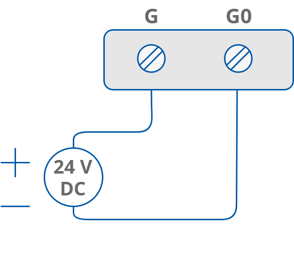
Power Supply Connection
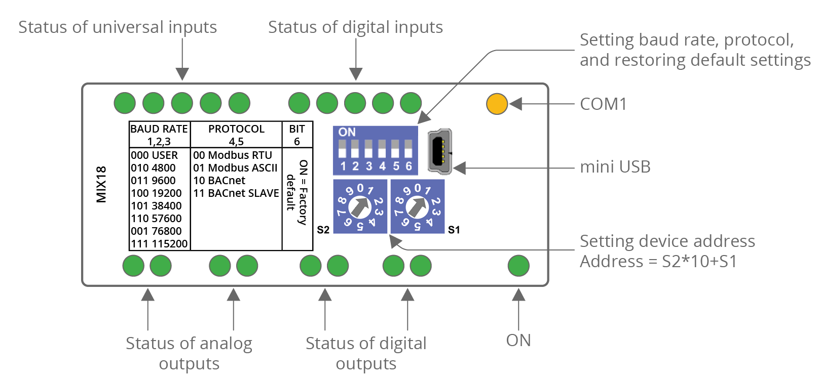
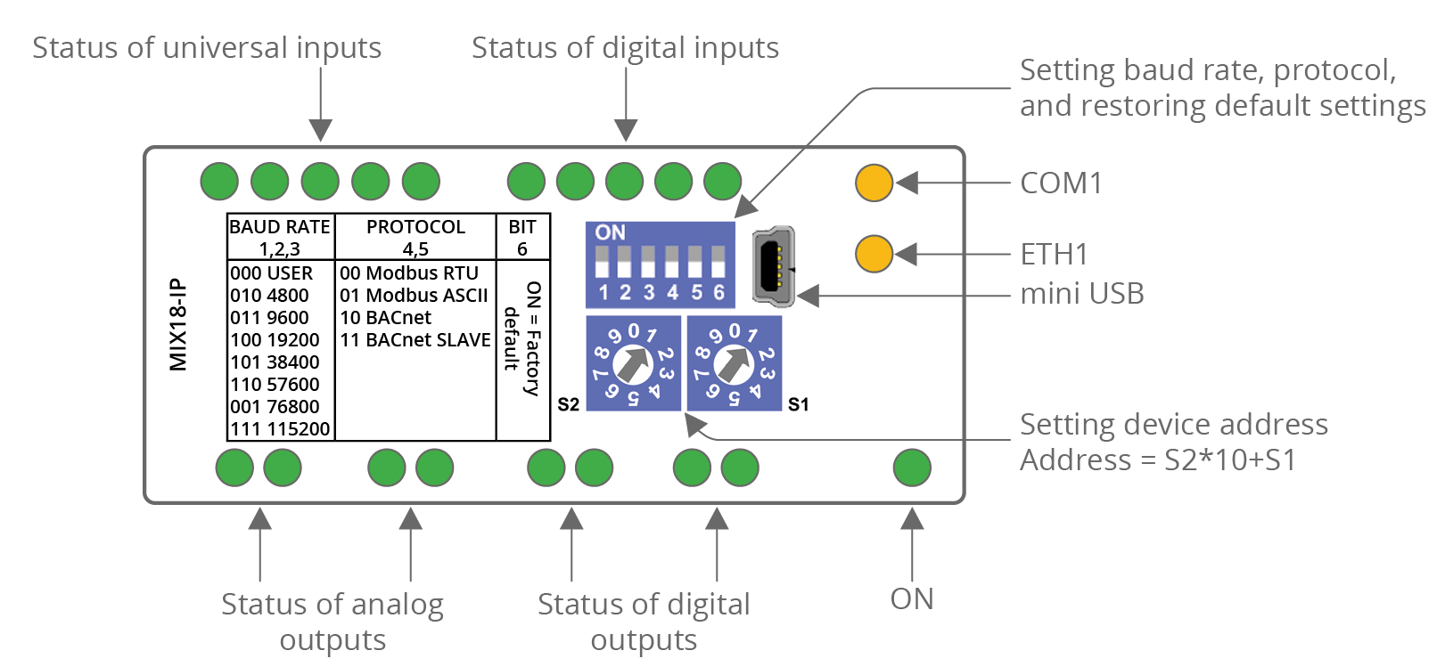
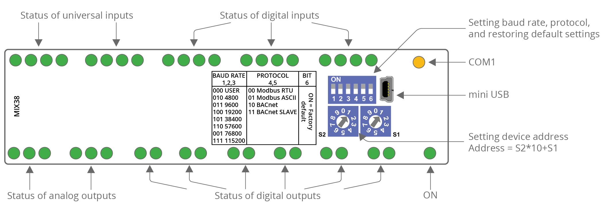
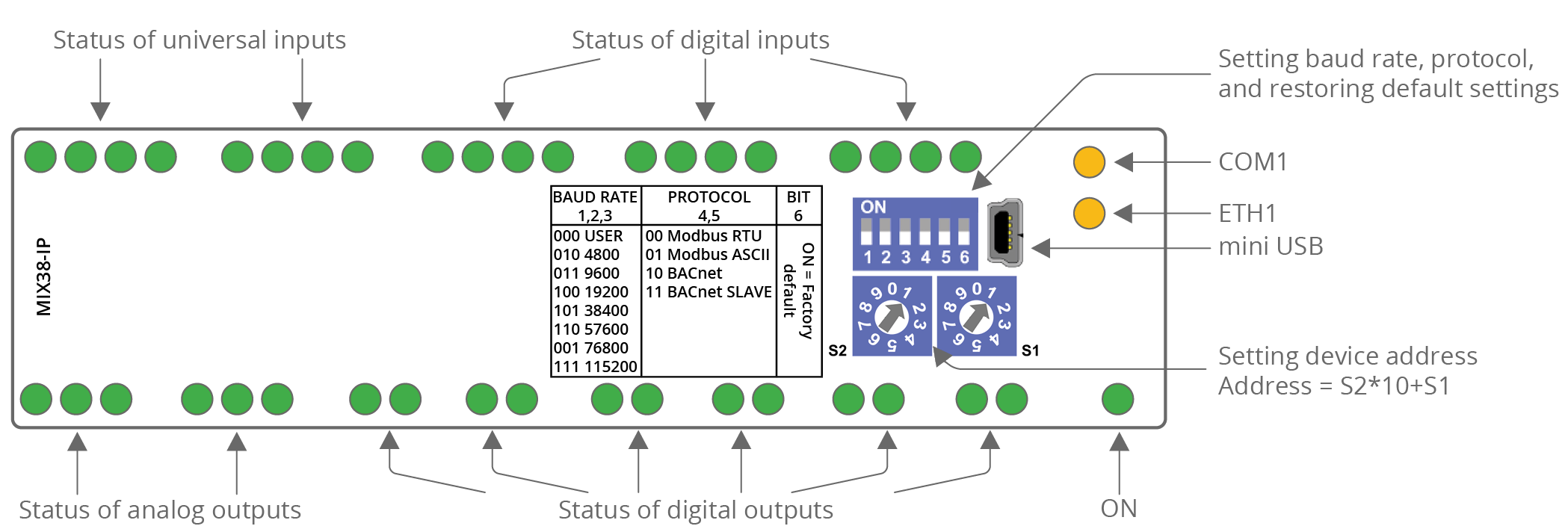
Front Panel LED Indicators
The front panel of the Multiprotocol I/O modules features an openable lid that ensures protection to the USB interface, DIP and rotary switches once the module is assembled in the control cabinet. For initial configuration, the lid must be opened using a flat-head screwdriver to provide access to the interfaces located beneath it.
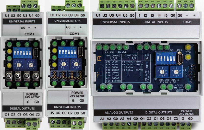
MIX Series Front Panels
MIX18
|
|
MIX38
|
|
MINI Series Front Panels
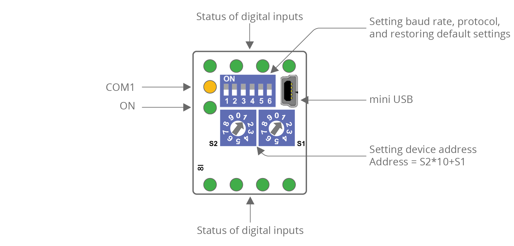
MINI 8I and 8I-IP
|

|
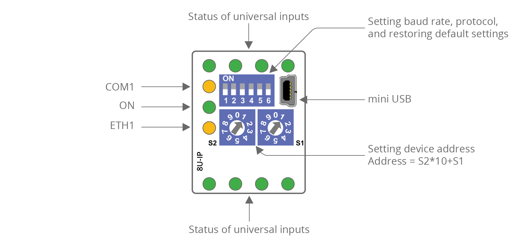
MINI 8U and 8U-IP

|
|
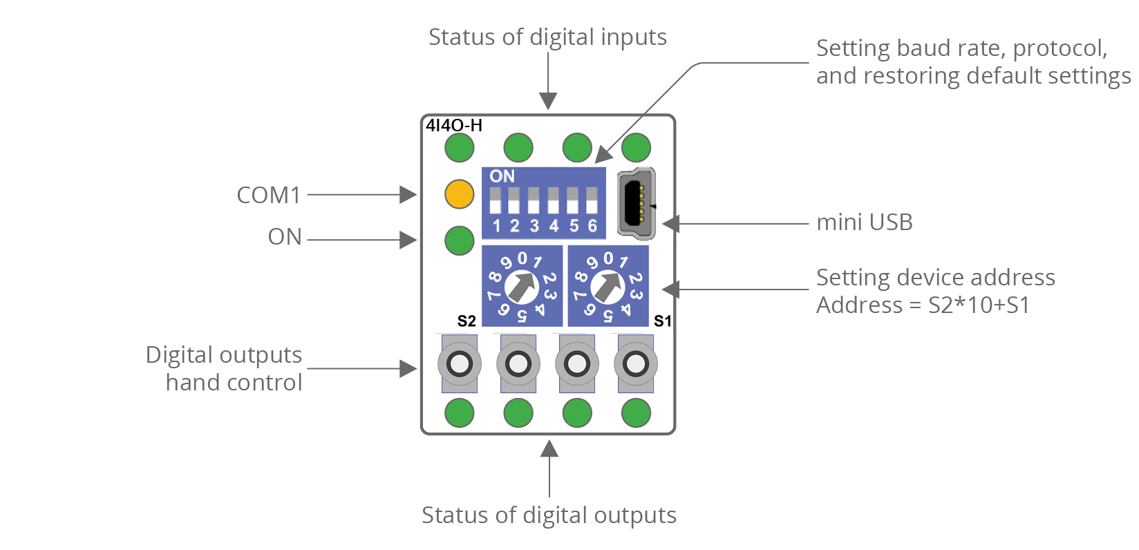
MINI 4I4O-H and 4I4O-H-IP
|

|
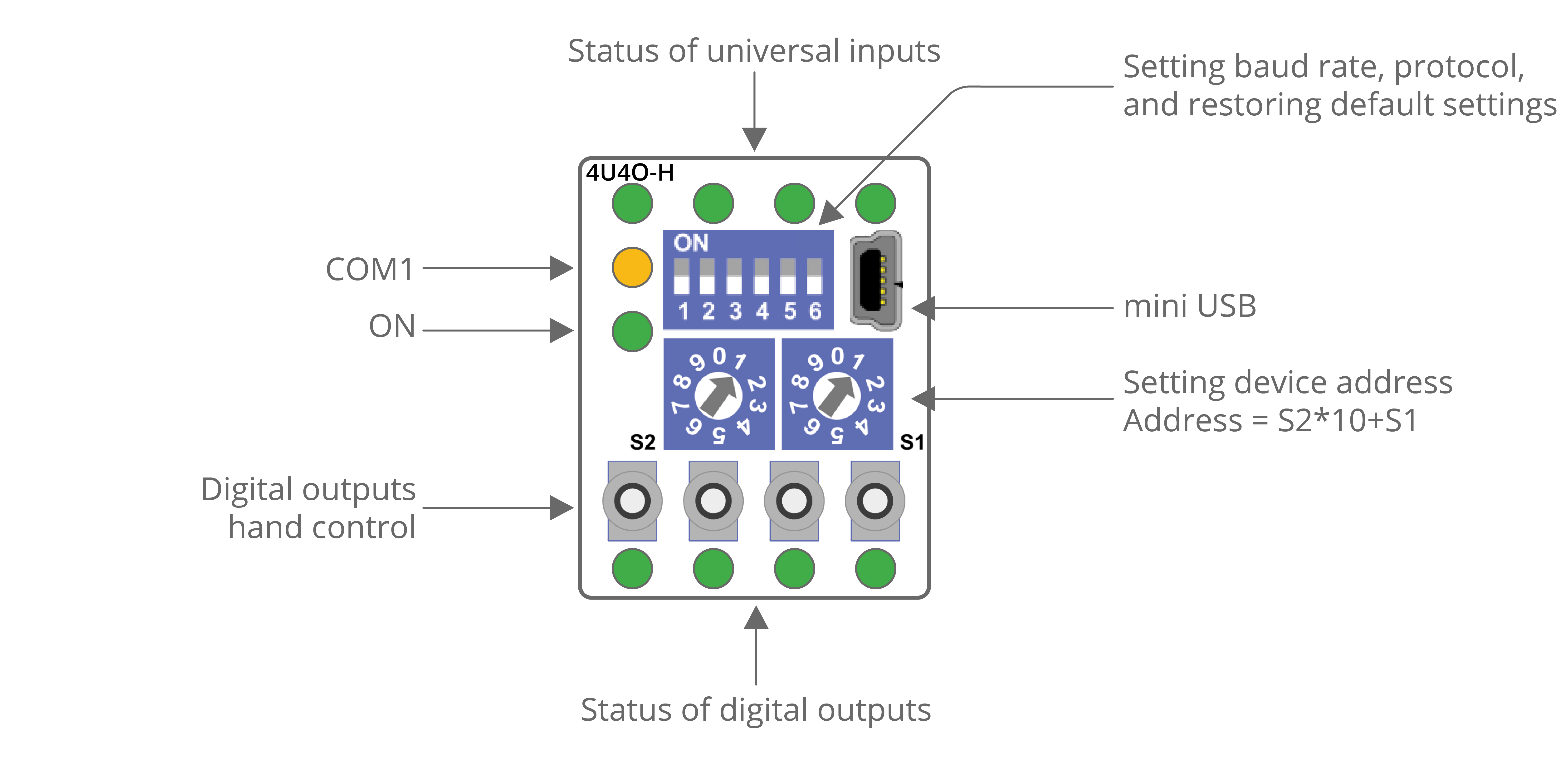
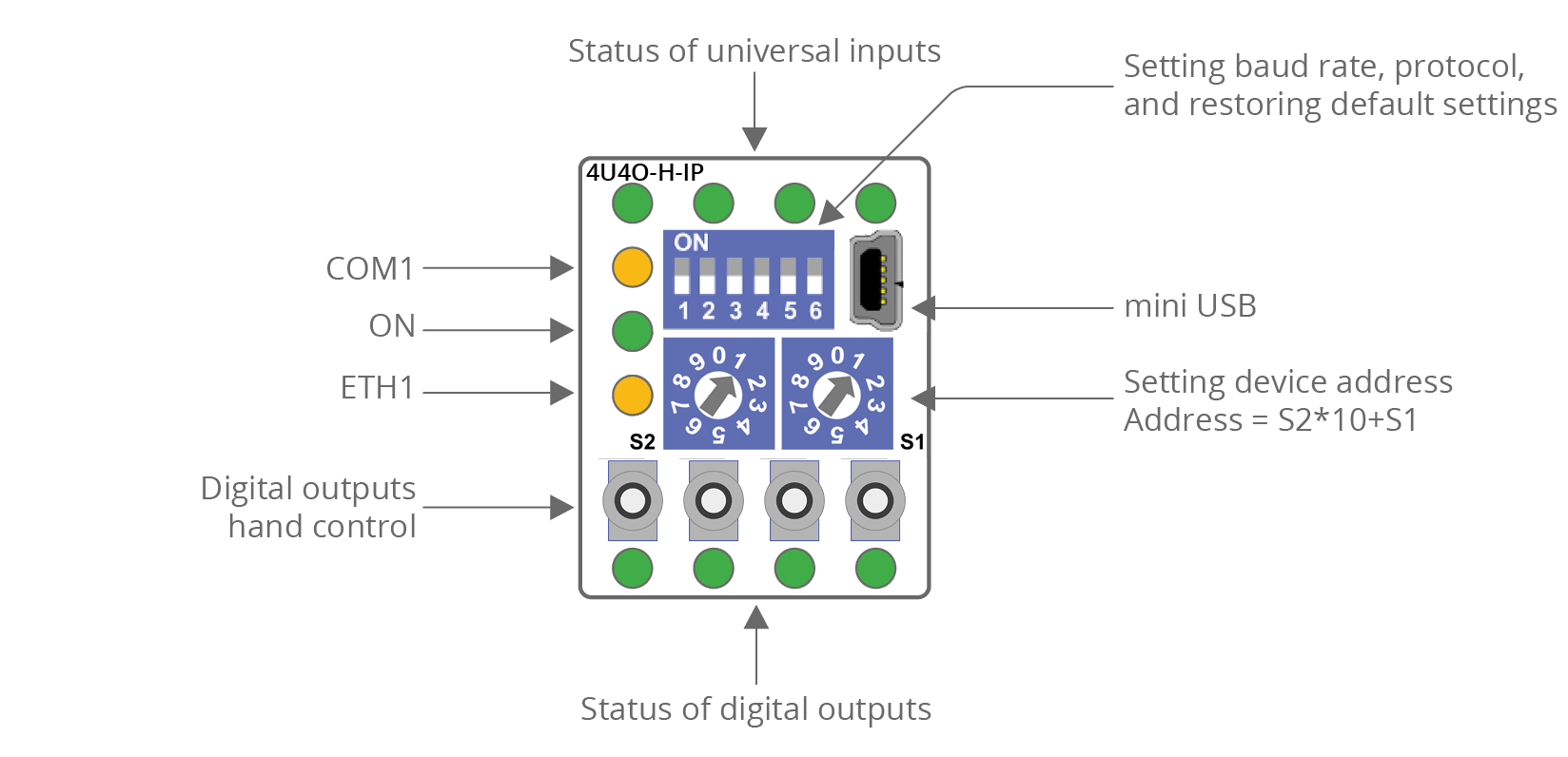
MINI 4U4O-H and 4U4O-H-IP
|
|
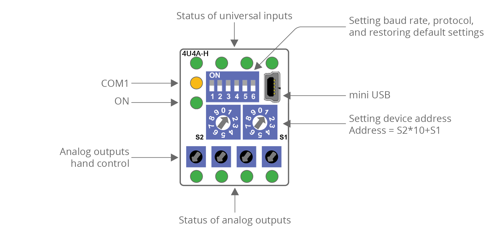
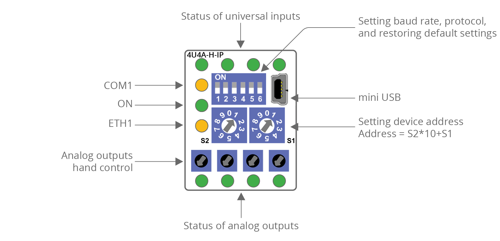
MINI 4U4A-H and 4U4A-H-IP
|
|
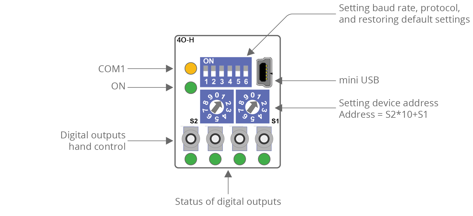
MINI 4O-H and 4O-H-IP
|
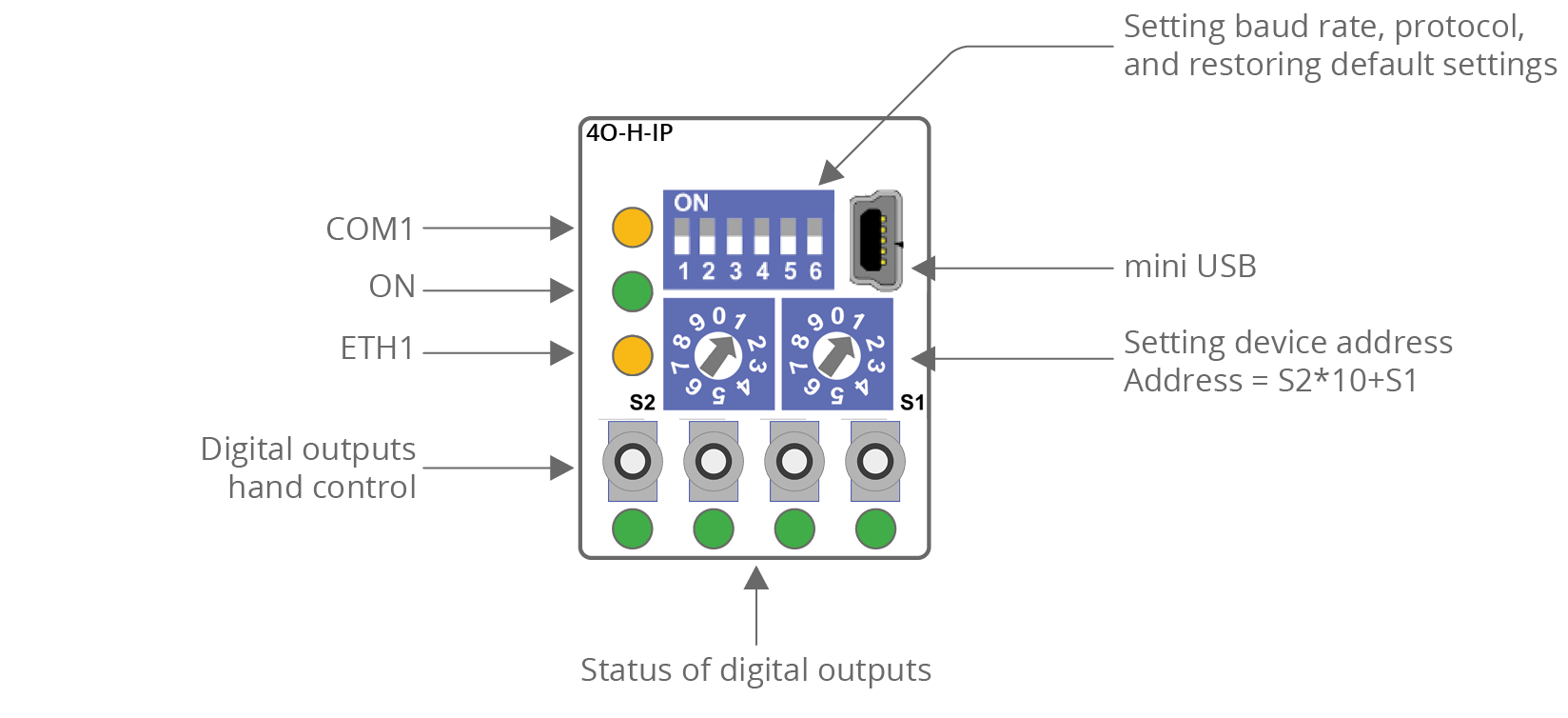
|
MINI 4TO-H and 4TO-H-IP

|
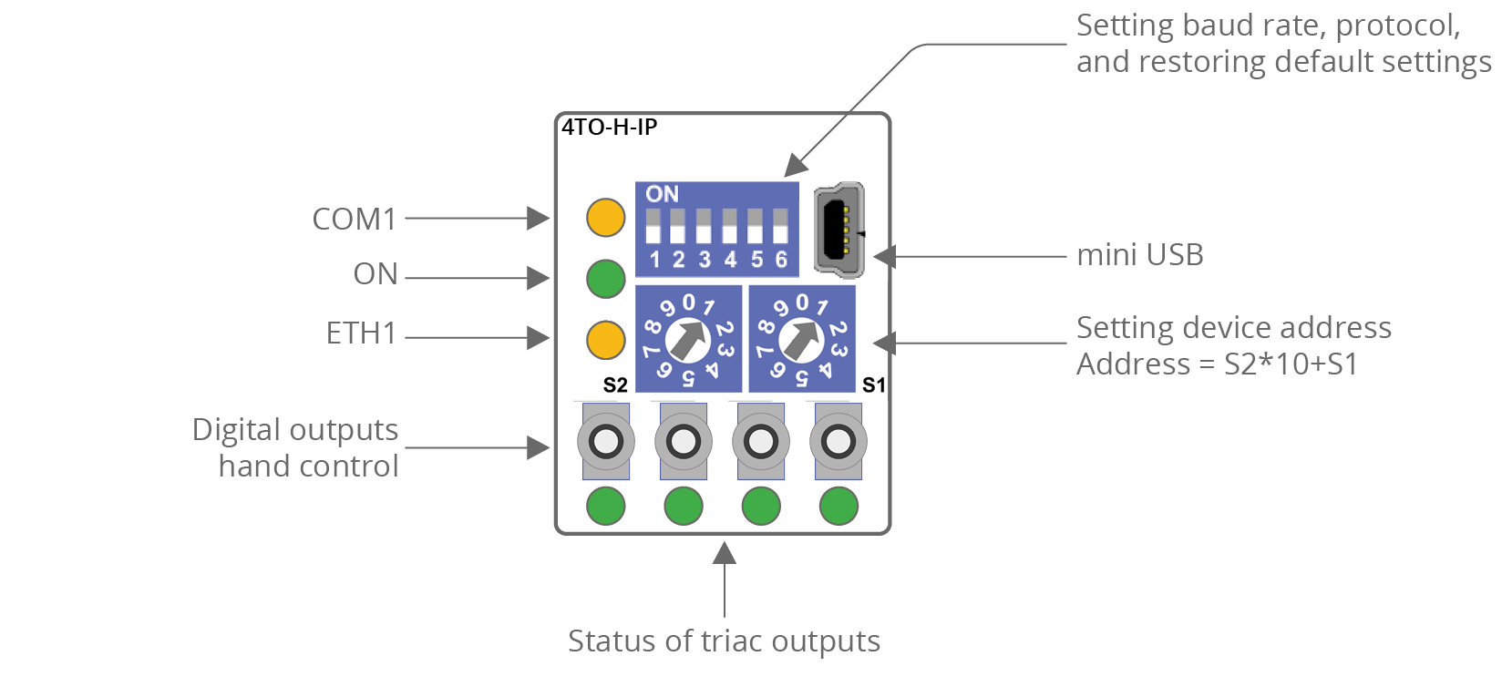
|
MAX Series Front Panels
MAX 12O-H and 12O-H-IP
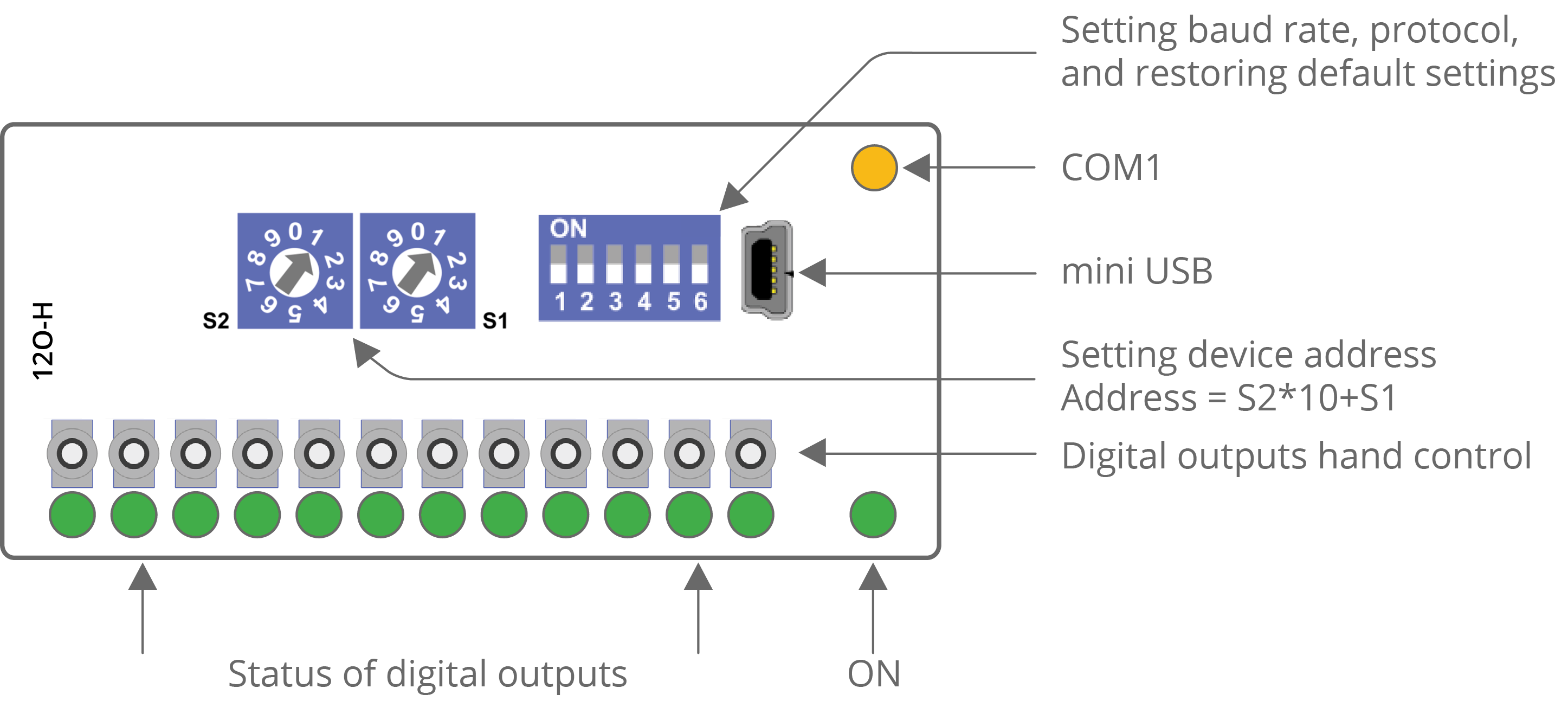
|
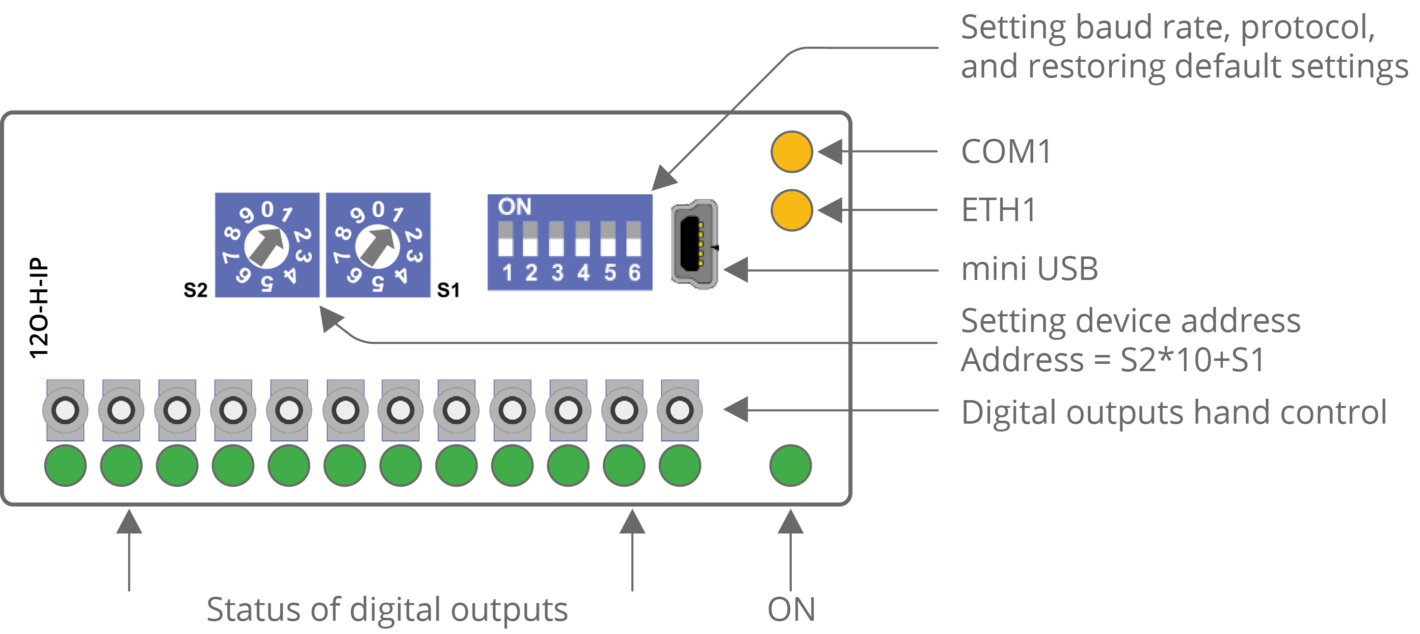
|
MAX 24I and 24I-IP
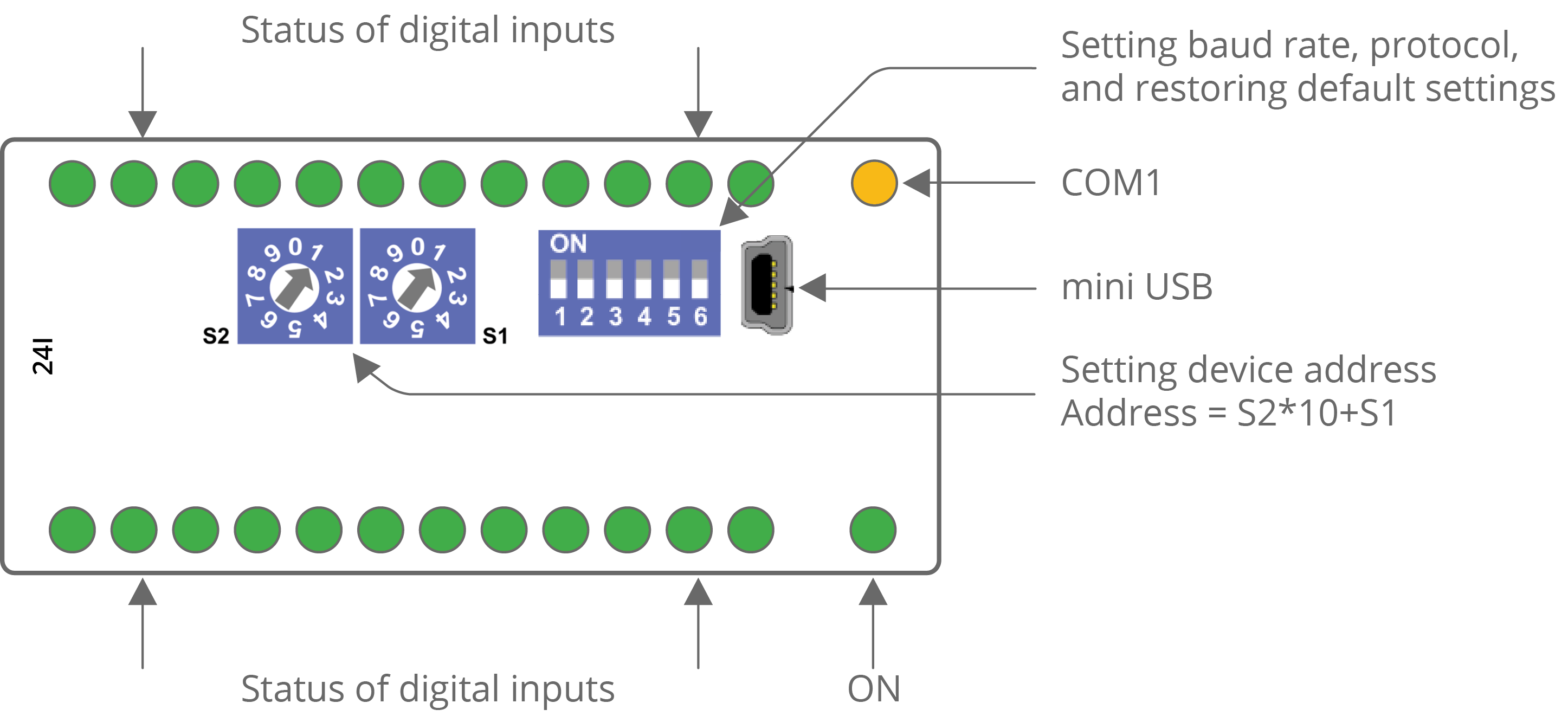
|
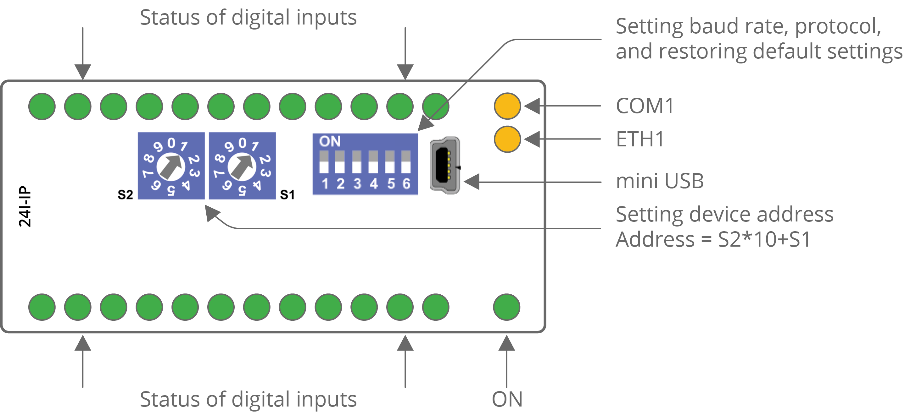
|
-
The power LED (ON) is on (green) if the module runs properly.
-
The communication LED (COM1) is on (orange) for 20 ms after sending each message. If the module receives/sends a lot of messages, the LED can be lit continuously.
-
The communication LED (ETH1) lights up (orange) in the transmit or receive state when sending/receiving each package through the Ethernet port. As long as the device sends/receives packages, the communication LED blinks continuously.
-
LEDs indicating the status of the universal inputs (U1-Un) are lit when the resistance connected to the input is less than 5 kΩ (dry contact input is active).
Warning!
The LED also lights up when the voltage connected to the input has a very low potential.
-
LEDs indicating the status of the digital inputs (I1-In) are lit when the input is active.
-
LEDs indicating the status of the analog outputs (A1-An) are lit when the output voltage or PWM duty cycle is greater than 0.
-
LEDs indicating the status of the digital outputs (O1-On) are lit when the output is enabled.
-
LEDs indicating the status of the triac outputs (TO1-TOn) are lit when the output is enabled or PWM duty cycle is greater then 0.