This document describes how to control iSMA-B-FCU cooling in analog and digital mode for fan coils.
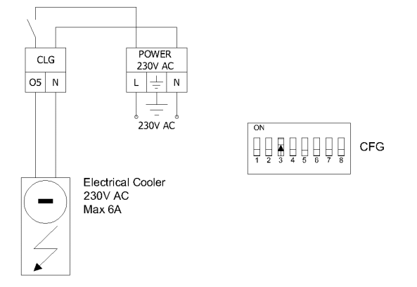
Dedicated output in iSMA-B-FCU for connecting an additional cooler is the O5 output. The second stage of cooling can be activated by switching the 'DIP switch' 3 to the 'ON' position.

Picture 1. Diagram of connection of an additional cooling device.
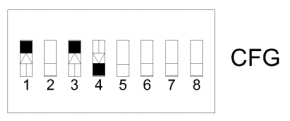
2. Digital mode

In this mode, the algorithm of the default application works with two outputs, exposing them to a PWM signal. In this configuration, we have two outputs TO2 and O5 at our disposal, the output A1, A2 is turned off by default. The principle of operation is similar to the operation of the first stage of cooling, except that the second stage works with an offset and is activated when one cooler does not have enough energy to cool the room or the set temperature must be reached quicker.
For additional knowledge about the variables in which the values are stored and how the algorithm is calculated, open the 'iSMA-B-FCU_Application_Manual_V1.3' manual on page 23 available on our website https://support.ismacontrolli.com.
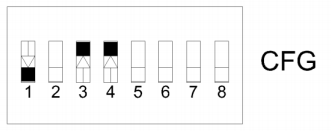
3. Analog mode

In this mode, the output value is calculated in the range of 0 - 100% through the PI controller included in the default iSMA-B-FCU application. There are three outputs A2 or TO2 and a dedicated output for the second heating stage O5.
For additional knowledge on the variables in which the values are stored and how the algorithm is calculated, open the 'iSMA-B-FCU_Application_Manual_V1.3' manual, page 24 available at our website https://support.ismacontrolli.com.
