In the Wire Sheet view there is also another method of selecting components and links. The method involves defining a rectangular area, which marks objects to be selected. It can either be a window selection or a crossing selection.
Both types require marking a square area in the Wire Sheet view by clicking in an empty area and dragging a rectangle over the objects to be selected. Release the rectangle, when all the selected objects are included.
Window Selection
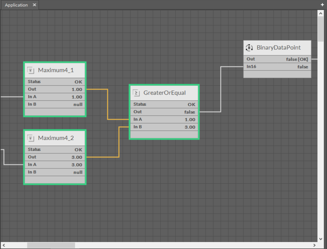
In case of a window selection, a rectangle dragged from the left to the right is blue. Only objects fully covered by the rectangle are selected (orange color); here, these are the Maximum and GreaterOrEqual components and their links. The remaining element has not been selected because it was not fully covered by the blue rectangle. The element dependent on the selected component and selected links is marked in green.

Window selection

Window selection
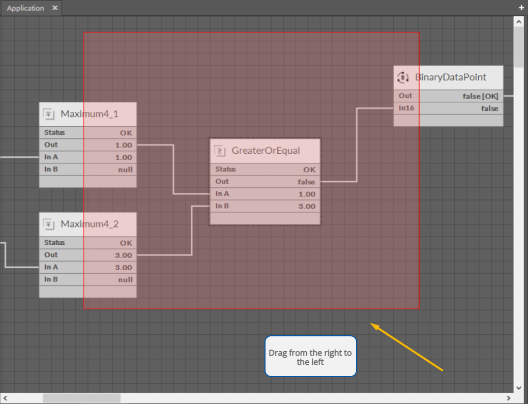
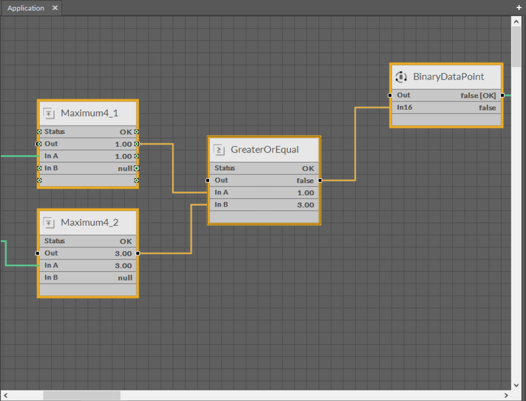
Crossing Selection
In case of a crossing selection the rectangle is dragged the opposite way, from the right to the left, and it is red. All the objects, even partially included in the rectangle, are selected (orange color); here, these are the Maxiumum, GreaterOrEqual, and Binary Data Point component along with their links.
Crossing selection
Crossing selection
The crossing selection method enables easy removal of all input links of the component without a need to individually select each link. For this purpose drag a narrow rectangle across the component’s links that are to be selected (see the figures below). All selected links (orange color) can be deleted with a Delete key or a context menu.

Crossing selection of links
Crossing selection of links