Airflow Control
Airflow in the VAV application is the main factor used to achieve a given temperature setpoint. The current airflow rate in l/s or cfm [V=K*sqrt(dP)] is calculated based on the differential pressure measurement using a built-in pressure transducer and the K-Factor variable.
K-Factor
The K-Factor variable, set in the calibration process from the Control Point VAV panel, iSMA Configurator, or BACnet/Modbus, is a parameter provided by the VAV box manufacturer. It determines the airflow through the unit at 1 Pa/1 inH2O.
The basic element enabling the regulation of the airflow stream is the measurement of its flow, which is obtained by measuring the pressure difference carried out on the measuring element (e.g., on the measuring cross) and performing appropriate mathematical calculations using the K-factor coefficient related to the VAV box.
Because the K-factor is determined at the factory laboratory-like conditions, it often requires modification by airflow calibration.
Additionally, the pressure transducer itself, although factory-calibrated, may require calibration during commissioning (zeroing).
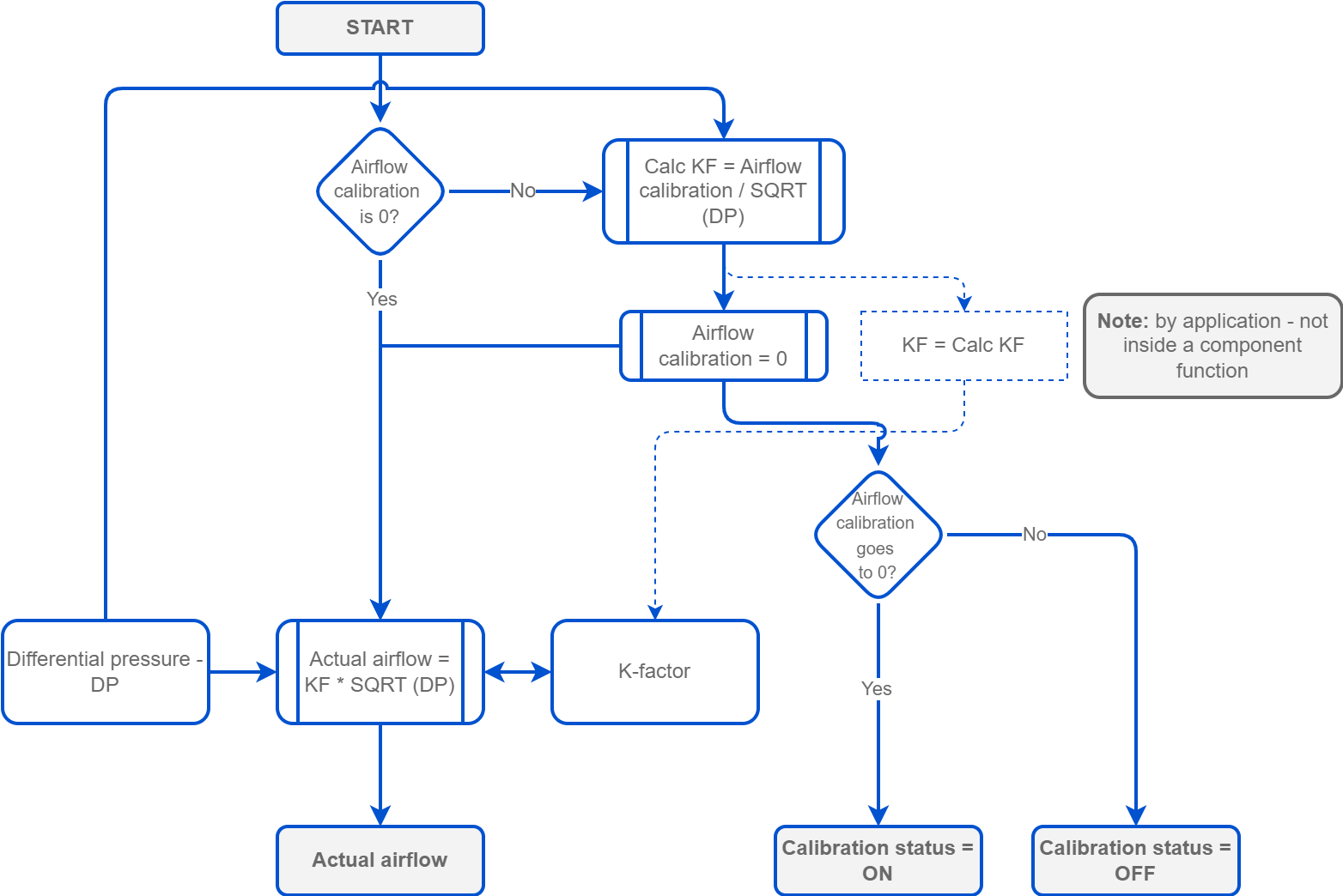
During the calibration process, the balancing technician takes the actual measurement of the airflow and enters the measured value into the AirllowCalibration component (in the AirFlowCalculator folder of the VAV application), triggering a recalculation of the pre-set K-Factor parameter so that the airflow indicated by the device corresponds to the actual airflow.
The built-in pressure transducer is also equipped with a zeroing function, available from the Control Point VAV panel, iSMA Configurator, or BACnet/Modbus (to obtain a zero measurement in the absence of airflow), which is performed in the absence of airflow (additionally, it is advisable to close the throttle) when the measured pressure difference is non-zero (minimal reading fluctuations are allowed due to measurement error).
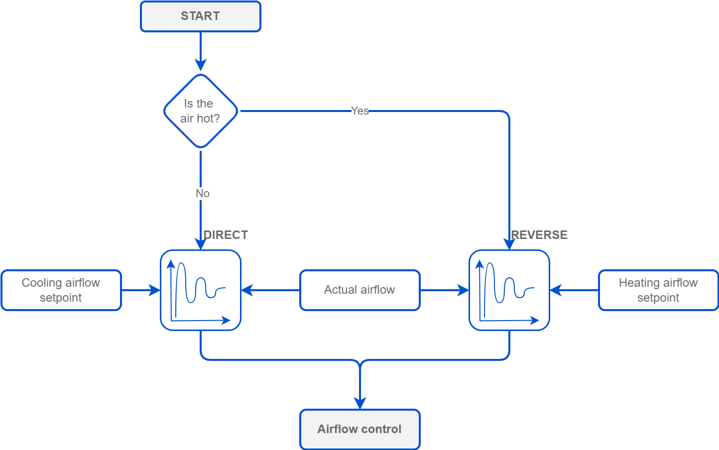
Concerning the output of the cooling or heating control loop and the specified airflow limits (in the occupied state), the current setpoint value for the airflow can be determined as a linear function.
The heating loop is used when hot air is detected (using a discharge air temperature sensor), and in the case of a system with a duct reheater, the airflow setpoint can be shaped as a linear function of the heating loop within the airflow limits (generally used as the 2nd heating stage) or as a constant minimum airflow setpoint for heating when the reheater is to be the main heat source (no Dual Heating).
Airflow Setpoint
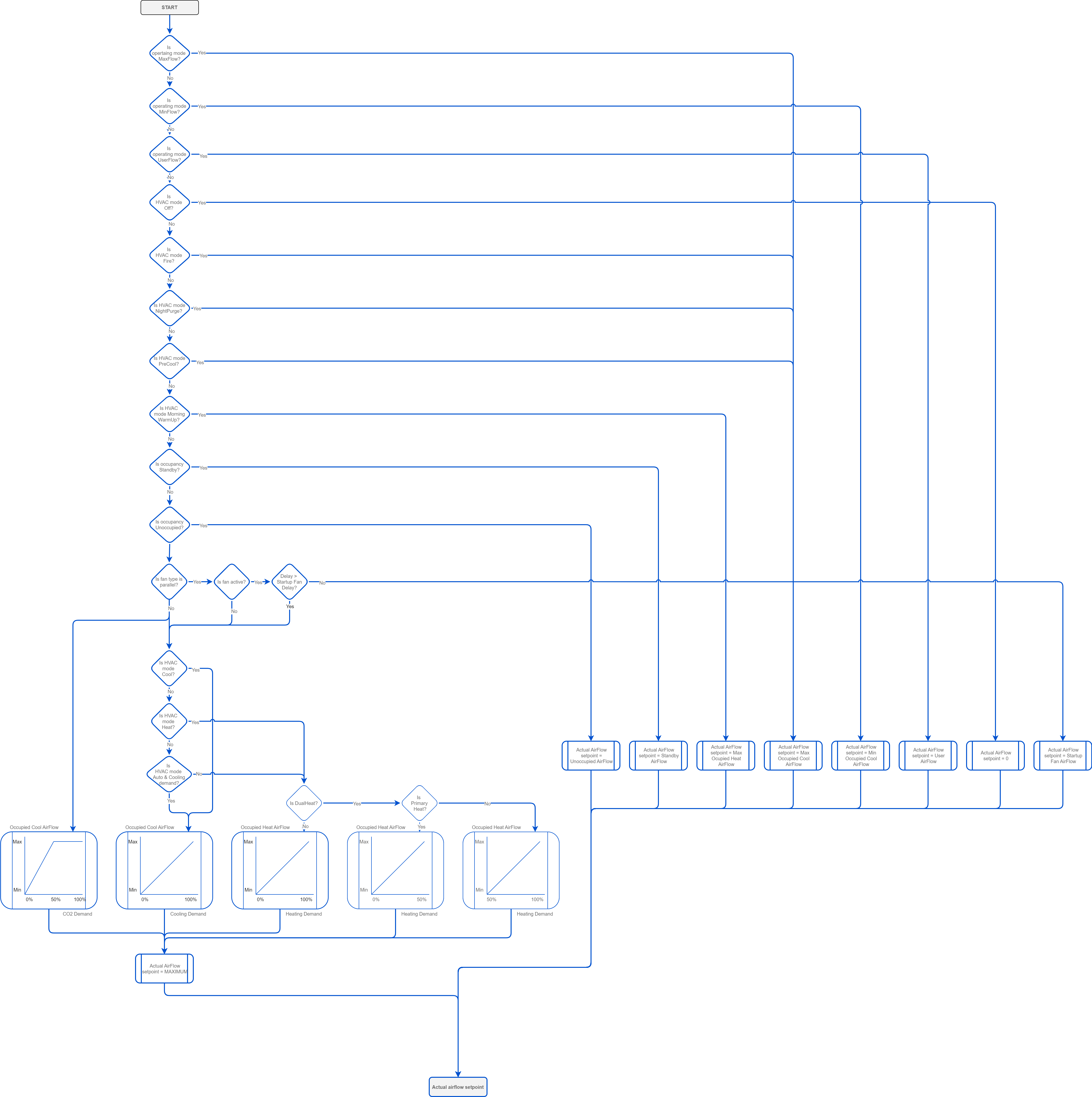
The airflow setpoint depends on the HVAC Mode settings (AirflowSetpointCalculator component) and may depend on the occupancy status.
-
Auto: in the Auto HVAC mode and the operating mode also set to auto, the airflow setpoint is determined by the occupancy status:
-
occupied and bypass:
-
heating: MaxOccHeatAirFlowSetpoint and MinOccHeatAirFlowSetpoint,
-
cooling: MaxOccCoolAirFlowSetpoint and MinOccCoolAirFlowSetpoint;
-
-
standby (StandbyAirFlowSetpoint) and unoccupied (UnoccAirFlowSetpoint): the setpoint is the same for heating and cooling.
-
By default, the maximum airflow setpoint for heating is set as half of the value of the airflow setpoint for cooling.
The setpoints are also determined by the demand resulting from the control loops calculated as a linear function between the minimum and maximum values for heating or cooling, respectively. The values resulting from the heating and cooling control loops are mutually exclusive, which means that only one of them sets the setpoint for the airflow (the other is off - it has a zero value).
-
Heat: the airflow setpoint is set depending on the occupancy status:
-
occupied and bypass: between the MaxOccHeatAirFlowSetpoint and MinOccHeatAirFlowSetpoint values - it is a function of the linear heating demand resulting from the heating control loop;
-
unoccupied (UnoccAirFlowSetpoint) and standby (StandbyAirFlowSetpoint), the airflow setpoint is identical to the Auto mode.
-
-
Cool: the airflow setpoint is set depending on the occupancy status:
-
occupied and bypass: between the MaxOccCoolAirFlowSetpoint and MinOccCoolAirFlowSetpoint values - it is a function of the linear cooling demand resulting from the cooling control loop;
-
unoccupied (UnoccAirFlowSetpoint) and standby (StandbyAirFlowSetpoint), the airflow setpoint is identical to the Auto mode;
-
-
MorningWarmUp: the airflow setpoint is set to the MaxOccHeatAirFlowSetpoint, regardless the occupancy status;
-
PreCool: the airflow setpoint is set to the MaxOccCoolAirFlowSetpoint, regardless the occupancy status;
-
NightPurge: the airflow setpoint is set to the MaxOccCoolAirFlowSetpoint, regardless the occupancy status;
-
Fire: the airflow setpoint is set to the MaxOccCoolAirFlowSetpoint, regardless the occupancy status;
-
Off: the airflow setpoint is set to 0, regardless of the occupancy status.
Notes
-
In addition, the airflow setpoint that would result from heating or cooling is affected by the value resulting from the increased CO2 concentration in the room resulting from the control loop, and it takes priority in setting the airflow setpoint as a linear function between the MaxOccCoolAirFlowSetpoint and MinOccCoolAirFlowSetpoint values (for cooling) over the heating or cooling demands.
-
In the case of a VAV box version with the parallel fan, when it is started and run for the period set in the StartupFanDelay (by default, 1 min), the airflow setpoint is set to the StartupAirFlowSetpoint value.