Installation
Learn how to install and start using the iC Device Manager: iC Device Manager.
The last tab in the iC Device Manager service is the Balancing tab. Here, it is possible to perform actions of the balancing process.
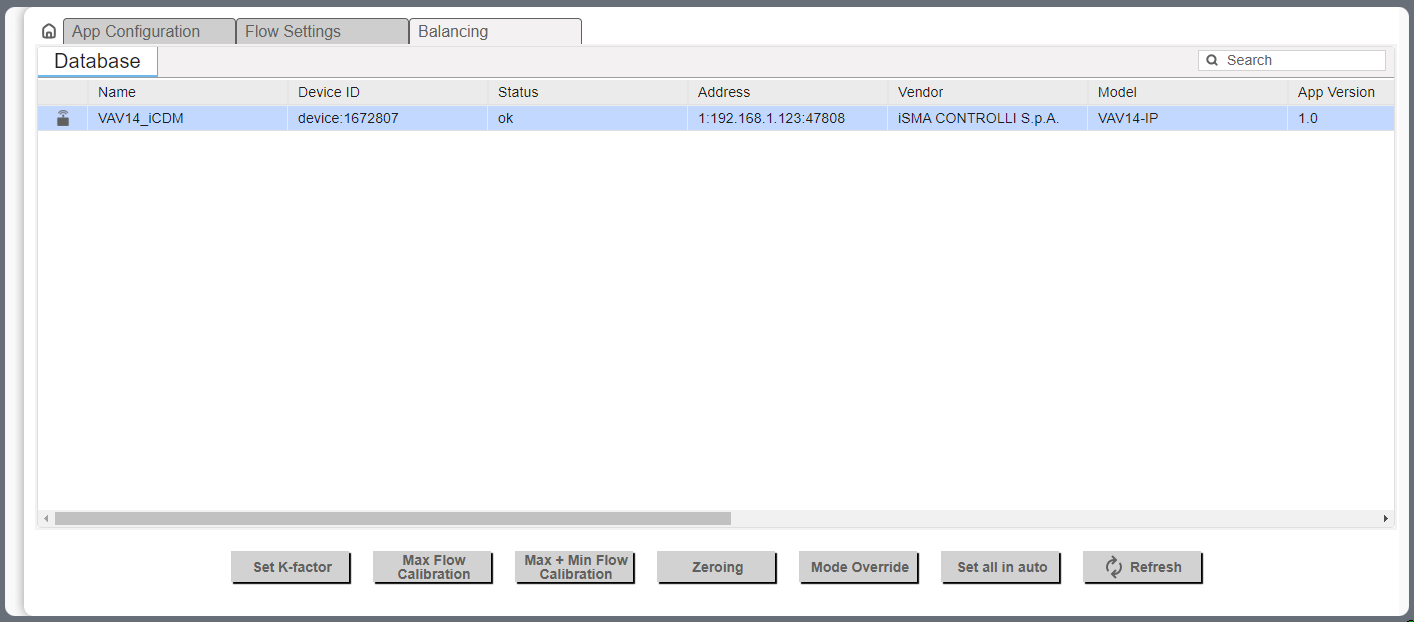
The main view of the tab shows data read from the device and available actions.
To make sure that the data are up to date, click the Refresh button.
The available actions are:
-
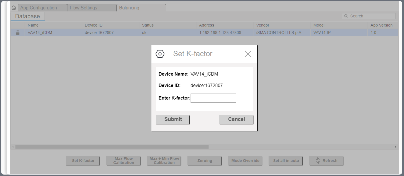
Set K-Factor: sets the K-factor value to the airflow calculations (AV61, 40289);
-
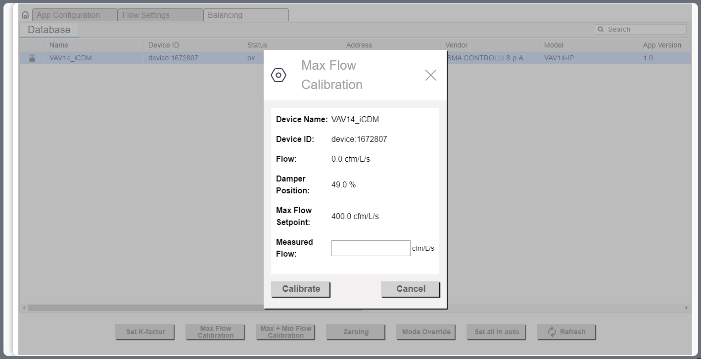
Max Flow Calibration: executes a calibration action according to a new maximum airflow value (AV66, 40294);
-
Max + Min Calibration: executes a calibration action according to a new maximum and minimum airflow values (AV66, 40294);
-
Zeroing: performs the pressure sensor zeroing action (BV13, 00014);
-
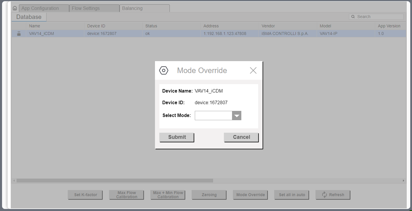
Mode Override: allows to force the device to operate in one of the available modes (MSV7, 40068):
-
Available settings: Auto, Max. Flow, Min. Flow, User Flow, User Position, Full Open, Full Close, Calibrate;
-
-
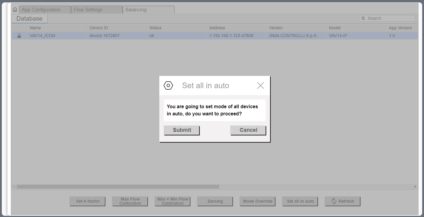
Set all In auto: forces all dampers to the Auto mode (MSV7, 40068).
Balancing Steps
To perform the balancing process and regulate the efficiency point of the ventilation system, follow the below steps. These activities are to performed in the presented order. If required, perform the balancing process with zeroing, however, according to the specific user and accuracy requirements, it is possible to omit the pressure sensor zeroing and/or minimum airflow calibration.
Balancing with zeroing
-
Pressure sensor zeroing.
-
Set the factory K-factor.
-
Measure the airflow and enter the value in the designated field.
-
Perform the maximum airflow calibration.
-
Measure the airflow and enter the value in the designated field.
-
Perform the minimum airflow calibration.
Balancing based on the maximum and minimum airflow calibration
-
Set the factory K-factor.
-
Measure the airflow and enter the value in the designated field.
-
Perform the maximum airflow calibration.
-
Measure the airflow and enter the value in the designated field.
-
Perform the minimum airflow calibration.
Balancing based on the maximum airflow calibration
-
Set the factory K-factor.
-
Measure the airflow and enter the value in the designated field.
-
Perform the maximum airflow calibration.
Pressure Sensor Zeroing
If required, pressure sensor zeroing is an initial action of the balancing process. According to the specific user and accuracy requirements, this action can be omitted in the balancing process.
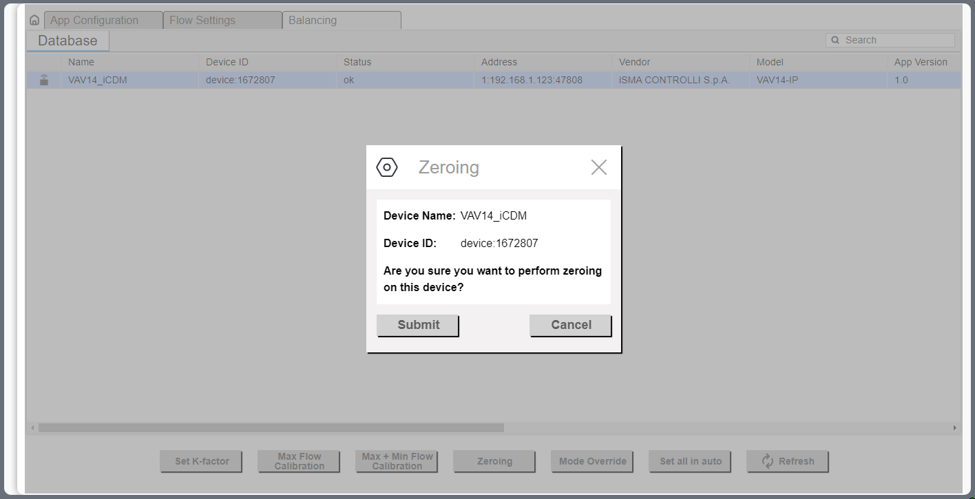
Pressure sensor zeroing is a part of the VAV balancing process, which aims at eliminating a constant measurement error of differential pressure on a built-in pressure sensor. The zeroing process involves the following steps:
-
Make sure the differential pressure sensor is disconnected from the measuring cross or other measuring method.
-
Use a flexible hose of an appropriate diameter to connect the two spigots (+ and -).
-
Make sure the hose is well secured and tight to equalize the pressures on both ports.
-
Invoke the zeroing action.
-
Detach the hose.
-
Restore the normal connection of the sensor to the measuring cross or other target circuit, pay attention to the polarity.
Setting K-factor
Setting the K-factor is a mandatory part of the balancing process. It is normally provided by the manufacturer of the VAV box. If for any reason it is unavailable, it is recommended to use a default K-factor from the VAV application (100 l/s /1000 cfm).
Maximum and Minimum Calibration
To perform the full balancing process, proceed to the maximum and minimum airflow calibration action, under the Max. + Min. Calibration button. The action invokes two pop-up windows, first for the maximum calibration in step 1, and second for the minimum airflow calibration in step 2.
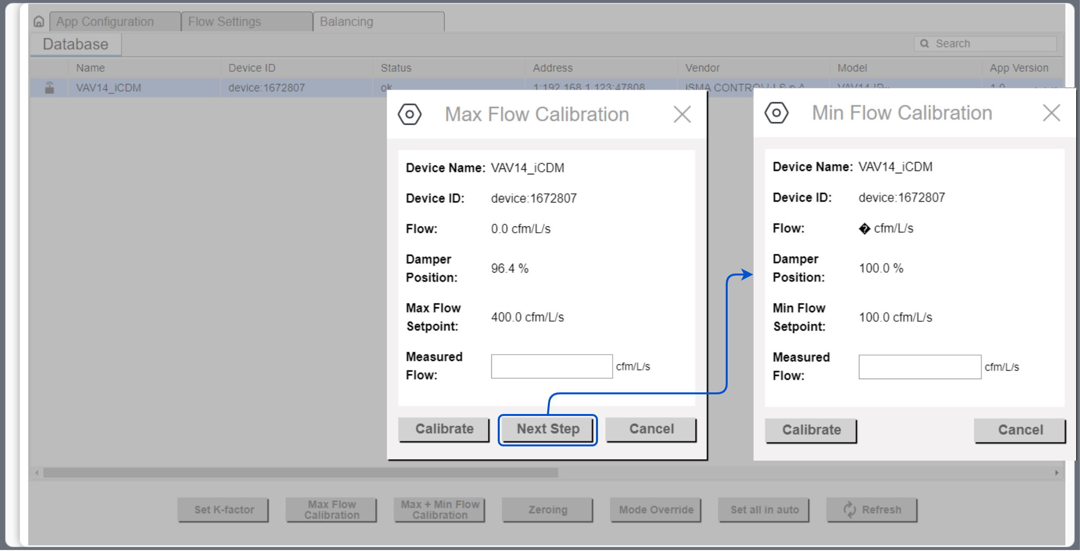
In step 1, measure the airflow and enter the measured value. Then, proceed to calibration (using the Calibrate button). The action will return a newly calculated K-factor.
After completing step 1, continue to step 2, the minimum airflow calibration. Enter the measured airflow value and use the Calibrate button.
Maximum Calibration
If, for any reason, the minimum airflow calibration is not required, it is possible to perform only the maximum airflow calibration. Measure the airflow and enter the measured value. Then, proceed to calibration (using the Calibrate button). The action will return a newly calculated K-factor.
Other Actions
Mode Override
The Mode Override action allows to force an operating mode to a damper. Available modes are:
-
Auto: sets auto mode (VAV application logic takes control),
-
Max flow: goes to a maximum airflow,
-
Min flow: goes to a minimum airflow,
-
User flow: goes to a user-set airflow,
-
User position: goes to a user-set position (% of damper opening),
-
Full open: damper fully open,
-
Full close: damper fully closed,
-
Calibrate: performs a damper calibration (the damper goes to 100%, than to 0%, and goes back to the control loop output).
Set All in Auto
The Set All in Auto action forces all dampers to the Auto operating mode.
Using iC Device Manager
Adding the Module
The iC Device Manager service is a part of the iC Workbench and iC Niagara Expansion Pack (from version 4.14).
Note: For a correct operation of the iC Device Manager service, it is required also to have the latest iClib version.
To start using the iC Device Manager service, go to the Palette window (in iC Workbench or other Niagara tool) and select the Open Palette option.
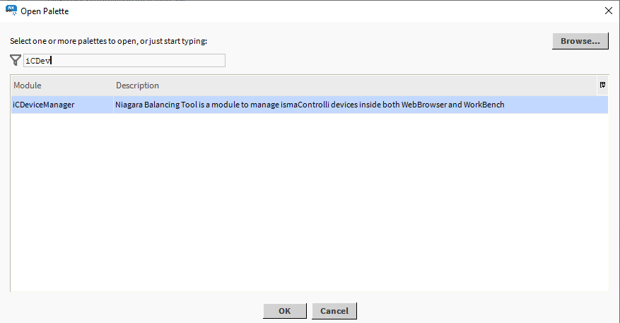
Confirm with OK, the palette is ready to use in the Palette window.
The only location where the service will operate properly is Config → Services.
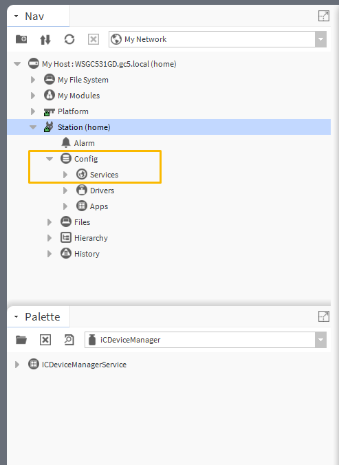
Drag and drop the iC Device Manager service to Services.
Warning!
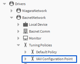
For the iC Device Manager service to fully operate, make sure that the VAV14-IP controller is added to the BACnet network in Drivers.
If BACnet has been configured using the default BACnetNetwork module, it is required to add the VAV Configuration Point (from the iSMA_CONTROLLI-Library) to Tuning Policies:
Adding the VAV Device
Offline
-
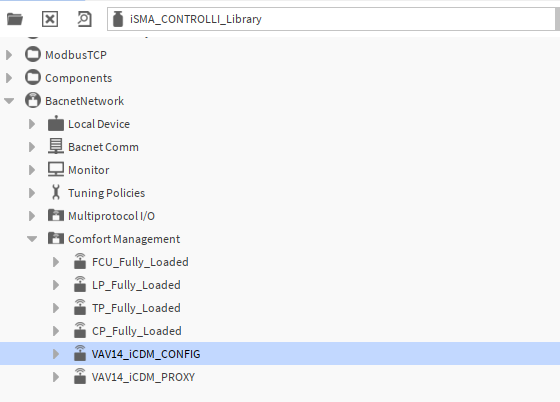
Add the VAV14-IP device from the iSMA_CONTROLLI_Library (BACnetNetwork → ComfortManagement), according to user requirements: VAV14_CONFIG_POINT or VAV14_PROXY_POINT.
-
Go to BACnetNetwork in the station and invoke the Discover action.
-
Mark the offline device and the device to be matched with it, and confirm with the Match button.
Online
-
Go to BACnetNetwork in the station and invoke the Discover action.
-
Add the discovered VAV14-IP device(s).
-
From the iSMA_CONTROLLI_Library select points for devices to be configured as proxy or config points.
Warning!
For a proper recognition of the device, the iC Device Manager verifies its hardware type, firmware version, and application version. From these values, only the application version is read from the AI 100 point. Make sure it is added to the device, otherwise, it may not be visible in the service.
Proxy and config points
Proxy points are BACnet points configured as proxy and placed under the Points folder. These consume Niagara license points.
Config points are BACnet points configured as config and placed under the Config folder. These points do not consume Niagara license points.