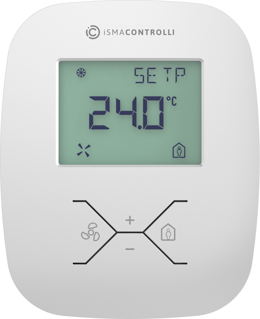
The iSMA-B-LP is a wall panel with 2.3” LCD display and four function buttons. Additionally, the panel has a built-in temperature sensor and, optionally, humidity and CO2 sensors.
The iSMA-B-LP is powered with 24 V AC/DC and has a built-in RS485 port (Modbus RTU/ASCII and BACnet MS/TP). The use of open communication protocol allows to connect the panel with any controller, which supports Modbus RTU/ASCII or BACnet MS/TP. Connected to the iSMA controllers, the panel allows to change the basic parameters such as: temperature setpoint, fan speed, FCU mode, and other. Thanks to a built-in USB port, there is a possibility of updating firmware and configuring the panel without the need of power supply. The iSMA-B-LP has modern design and is available in different colors (white is basic), on client’s request.
Room Panel Versions
The iSMA-B-LP room panels are available in four different configurations, depending on installed sensors, available parameters, and settings.
All possible sensors’ configuration versions are listed in the table below.
|
Ordering |
Temperature |
Humidity |
CO2 |
|---|---|---|---|
|
iSMA-B-LP(-1) |
|
|
|
|
iSMA-B-LP-H(-1) |
|
|
|
|
iSMA-B-LP-C(-1) |
|
|
|
|
iSMA-B-LP-HC(-1) |
|
|
|
Room panel versions of sensors configuration
Each of the available room panel versions can be equipped with either one variant of the keypad icons set:
-
standard (fan/occupancy menu icons, plus/minus selecting icons) and
-
optional (menu/check icons, up and down arrows selecting icons).
The ordering code for a standard keypad icons set panel version is iSMA-B-LP(-XX) (on the left), and for the optional icons set is iSMA-B-LP(-XX)-1 (on the right).
|

|
Dimensions
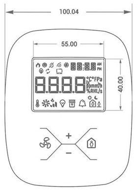
Front dimensions
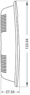
Side dimensions
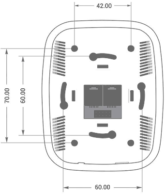
Back dimensions
Power Supply
The iSMA-B-LP room ranel is powered with 24 V AC/DC. The power consumption depends on the power supply voltage type used and the fact whether the CO2 sensor is installed (see the technical specification). There are two RJ12 sockets mounted on the back side of the room panel. Each RJ12 socket has the same internal connection and functionality. Two RJ12 sockets allow for using in and out connections for other devices in the network.
The power supply can be connected through the RJ12 connector as shown in the figure below.
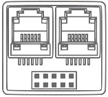
RJ12 sockets
There are two pairs of pins for the 24 V AC/DC power supply connection (+24 V DC pins 5 and 6, grounding pins 1 and 4). These pin pairs can be used freely. It is especially useful if different types of connection cables are used (4 or 6 core). It is possible to use a single cable with RJ12 connectors for the power supply and RS485 communication. Pins 2 and 3 are dedicated for the RS485 communication connection.
The room panel exchanges data with other devices through Modbus protocol (RTU/ASCII) and BACnet MS/TP.
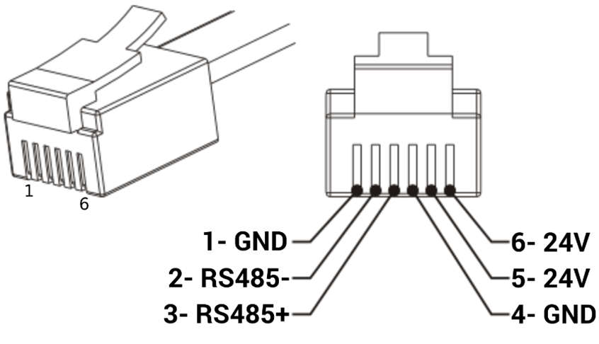
RJ12 pins
WARNING! In case of the RS485 connection, pay attention to a standard polarization. Connect RS485+ to pin 3 and RS485- to pin 2, as shown in the figure 4 above.
DC Power Connection
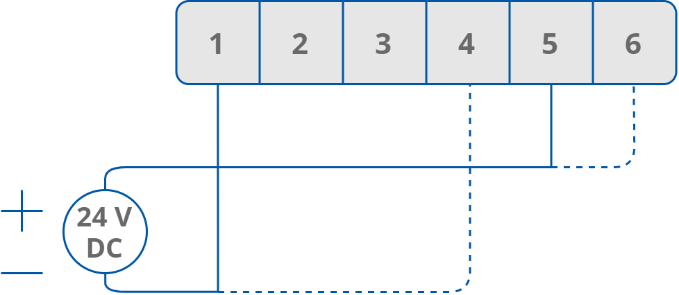
DC power connection
AC Power Connection
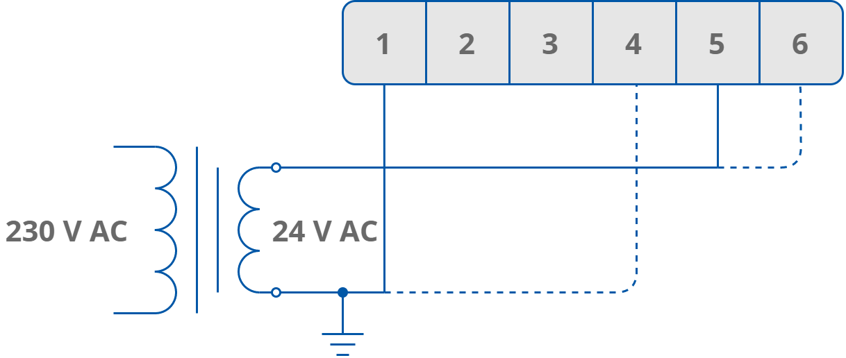
AC power connection
Communication
RS485 Communication Bus Connection
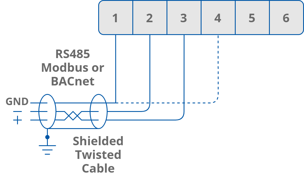
RS485 communication bus connection
Connecting Room Panels in the Network
It is possible to connect more than one room panels into the one network in a very simple way. An additional RJ12 socket can be used to connect another room panel by using one single cable. Every panel can exchange information within the network. The solution can be applied in large areas, when more than one room panels are needed. The maximum number of devices connected in one network is 128.
WARNING! The first and last device in the network need to have termination activated.
|
|
Max. 128 devices |
|
|
|
RJ12 |
RJ12 |
||

|
|
||
|
First device in the network |
Last device in the network |
||
RS485 Network Termination
Transmission line effects often present a problem for data communication networks. These problems include reflections and signal attenuation.
To eliminate the presence of reflections of signal from the end of the cable, the cable must be terminated at both ends with a resistor across the line adequate to its characteristic impedance. Both ends must be terminated since the propagation is bidirectional. In case of an RS485 twisted pair cable this termination is typically 120 Ω.
Each panel has a built-in termination resistor, which can be added to the network by setting the DIP-switch no. 2 to the ON position. The last and first room panels in the network need to have the termination activated.
Connecting a termination resistor by DIP switch no. 2
USB Port
The USB connection is dedicated for maintenance and settings.
The USB port (mini type B) is located at the bottom of the device.

USB port
The USB connection provides the power supply for the room panel (+5 V DC), therefore there is no need for additional power supply in this connection type.
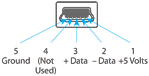
Mini USB pinout
Restoring Default Settings
To restore the default configuration of all registers, follow the below steps:
-
Turn the power supply off.
-
Set the DIP switch no. 1 to the ON position.

Position of the DIP switch no. 1 for restoring default settings
-
Turn the power supply on, the LCD display starts blinking.
-
Set the DIP switch no. 1 to the OFF position to restore the default settings. To cancel the reset, turn the power off and set the DIP switch no. 1 to OFF.
|
Register Name |
Default Value |
|---|---|
|
BAUD_RATE |
11520 (115200 bps) |
|
STOP_BITS |
1 |
|
DATA_BITS |
8 |
|
PARITY_BITS |
0 |
|
ADDRESS |
1 |
|
PROTOCOL |
0 (Modbus RTU) |
Default communication settings