VAV Cooling Only
The VAV cooling application is a configuration factory default; it does not require any further configuration of the reheater, perimeter, or fan. Other configuration parameters (such as device type – VAV or VVT, damper direction – CW or CCW, default sensor source, type and range or polarity, dual heating function, or heater priority) are available in the Control Point VAV panel or software programming tools (iSMA Configurator/iC Device Manager module/iC Tool).
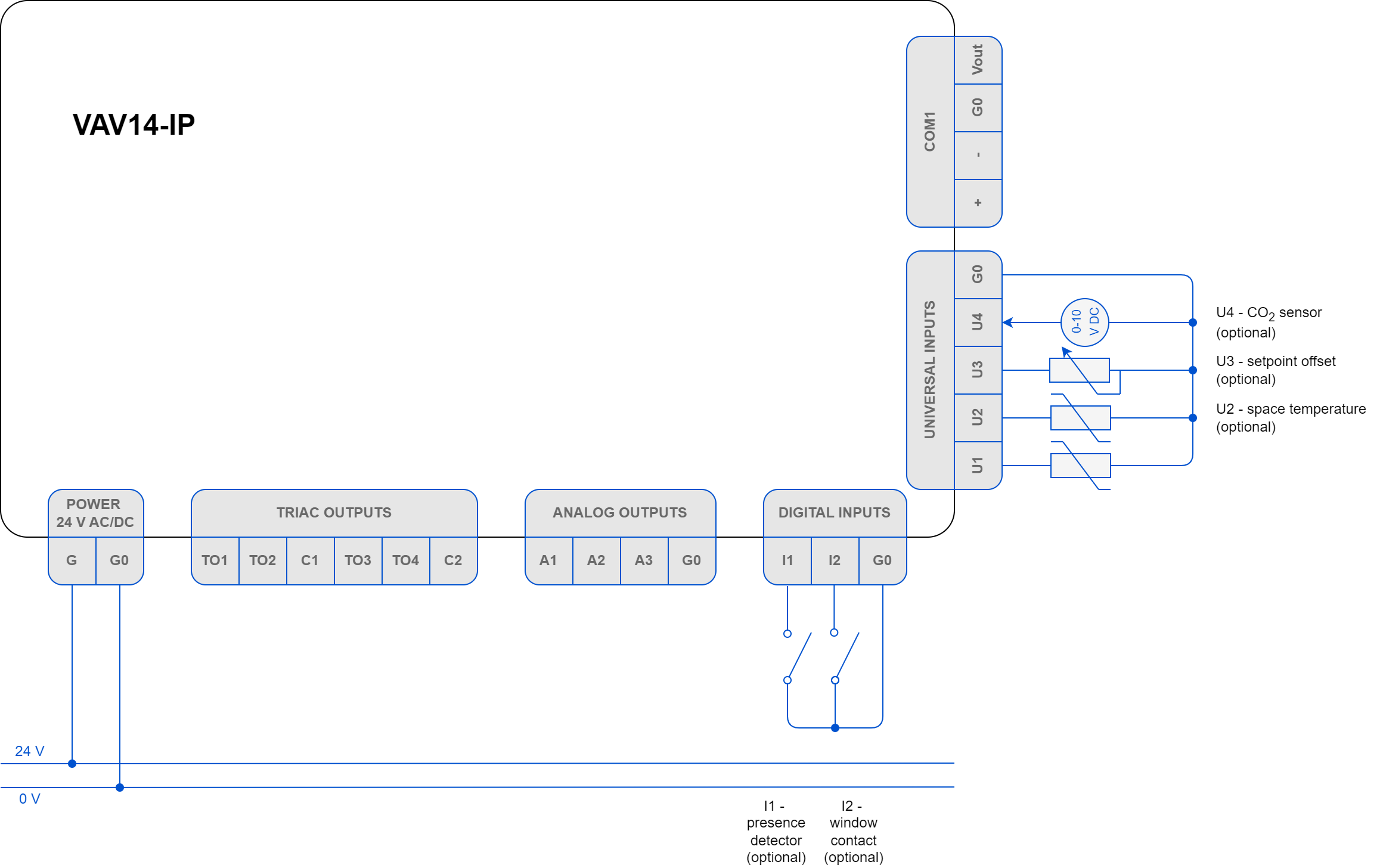
The Control Point VAV panel or sensors on inputs (space temperature, setpoint offset, CO2 sensor) are required for the application to operate properly. Optionally, it is possible to connect the presence detector and window contact sensors to minimize energy efficiency loss.
VAV Cooling/Heating
The VAV cooling/heating application does not require any further configuration of the reheater, perimeter, or fan. To enable the variant, use factory default configuration of the VAV cooling and connect the discharge air temperature (DAT) sensor. Other configuration parameters (such as device type – VAV or VVT, damper direction – CW or CCW, default sensor source, type and range or polarity, dual heating function, or heater priority) are available in the Control Point VAV panel or software programming tools (iSMA Configurator/iC Device Manager module/iC Tool).
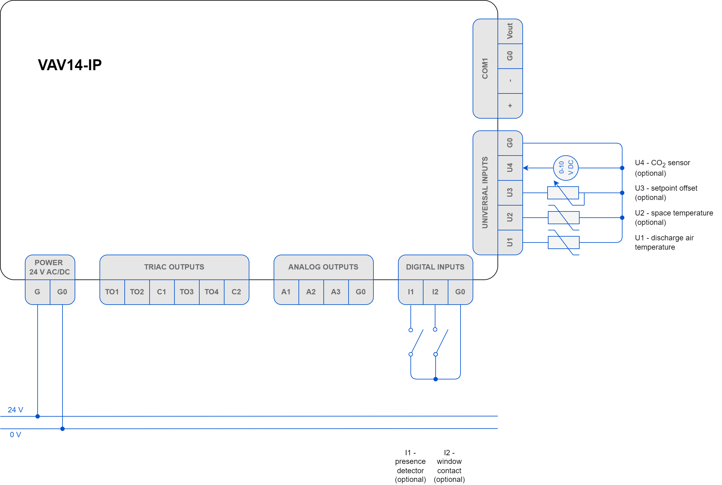
For the application to operate properly, it is required to connect the following elements:
-
Control Point VAV panel or sensors on inputs (space temperature, setpoint offset, CO2 sensor), and
-
DAT sensor.
Optionally, it is possible to connect the presence detector and window contact sensors to minimize energy efficiency loss.
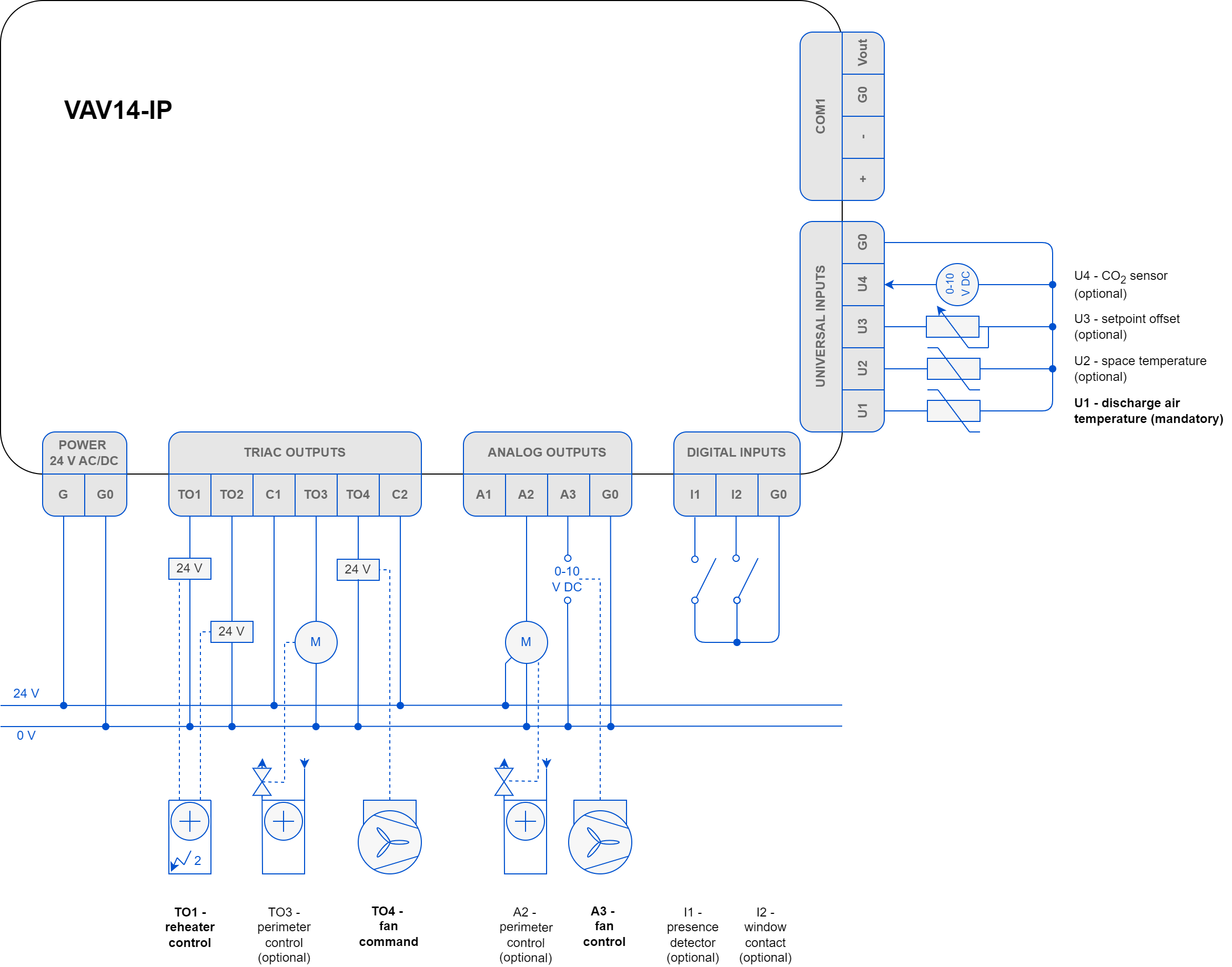
VAV with Water Reheater and Optional Perimeter
The VAV cooling with water reheater and optional perimeter application requires to configure the following parameters:
-
reheater’s control type (time proportional - PWM, digital, or floating),
-
(if applicable) perimeter’s control type (time proportional - PWM, on/off).
Configuring of any type of the reheater or perimeter automatically activates an analog control mode, so it does not require any further configuration.
Other configuration parameters (such as device type – VAV or VVT, damper direction – CW or CCW, default sensor source, type and range or polarity, dual heating function, or heater priority) are available in the Control Point VAV panel or software programming tools (iSMA Configurator/iC Device Manager module/iC Tool).
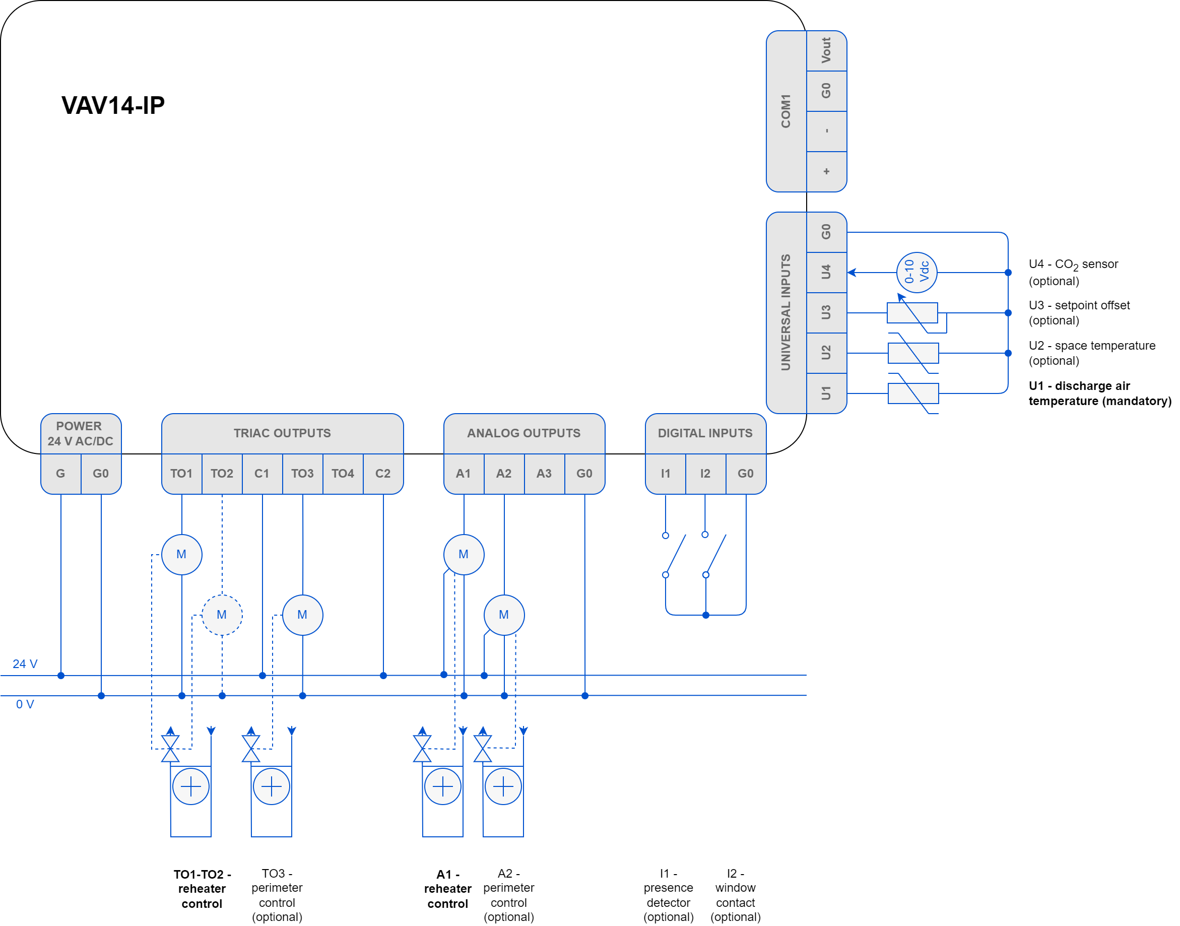
For the application to operate properly, it is required to connect the following elements:
-
Control Point VAV panel or sensors on inputs (space temperature, setpoint offset, CO2 sensor), and
-
DAT sensor located in the supply air duct before VAV.
Optionally, it is possible to connect the presence detector and window contact sensors to minimize energy efficiency loss. To control the reheater and, optionally, perimeter, dedicated triac and analog output are available, as depicted on the diagram above.
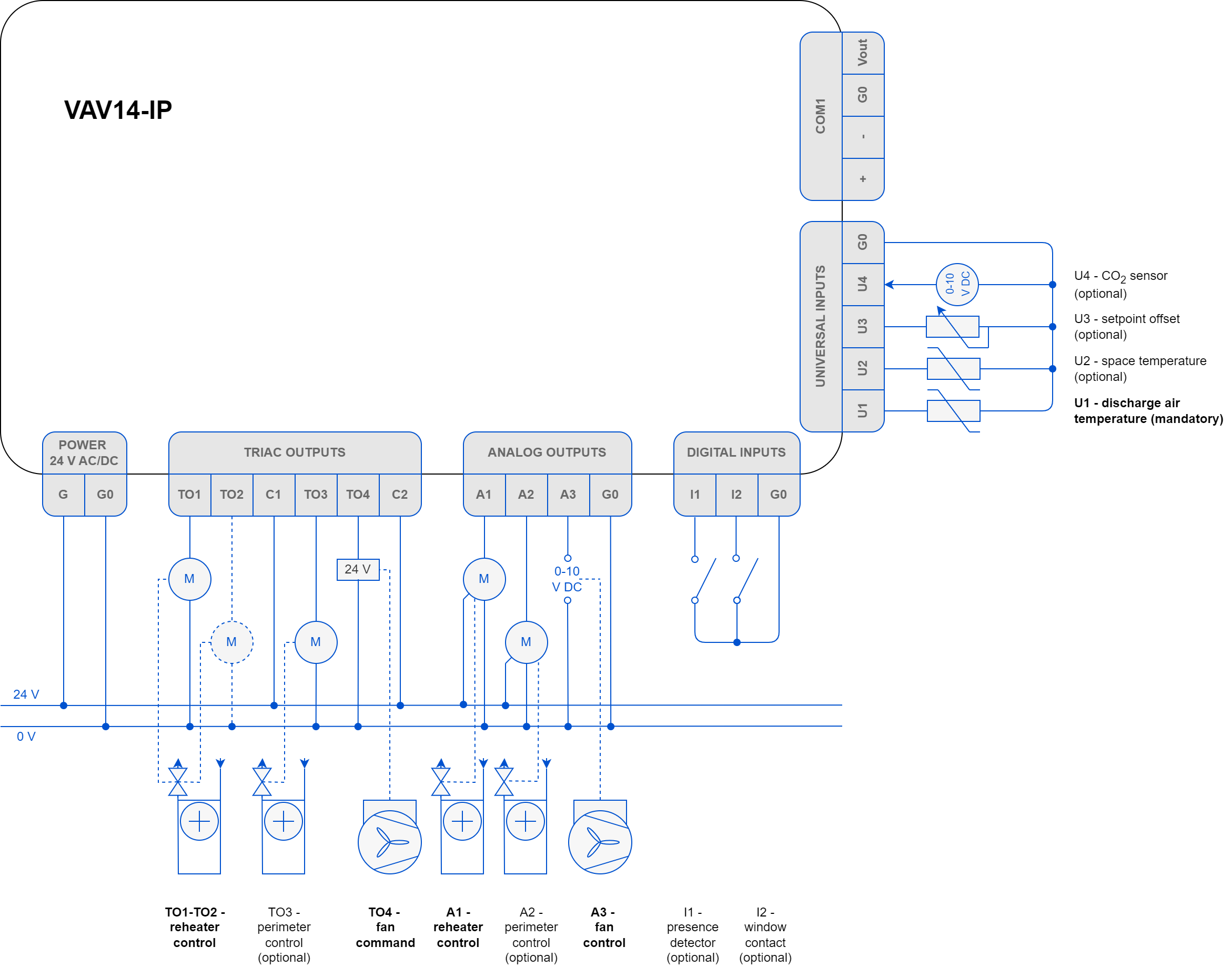
VAV with up to 2-stage Electric Reheater and Optional Perimeter
The VAV cooling with up to 2-stage electric reheater and optional perimeter application requires to configure the following parameters:
-
reheater’s control type:
-
1-stage reheater: time proportional (PWM), digital (on/off),
-
2-stage reheater: digital (on/off);
-
-
(if applicable) perimeter’s control type (time proportional - PWM, on/off).
Configuring of any type of the reheater or perimeter automatically activates an analog control mode, so it does not require any further configuration.
Other configuration parameters (such as device type – VAV or VVT, damper direction – CW or CCW, default sensor source, type and range or polarity, dual heating function, or heater priority) are available in the Control Point VAV panel or software programming tools (iSMA Configurator/iC Device Manager module/iC Tool).
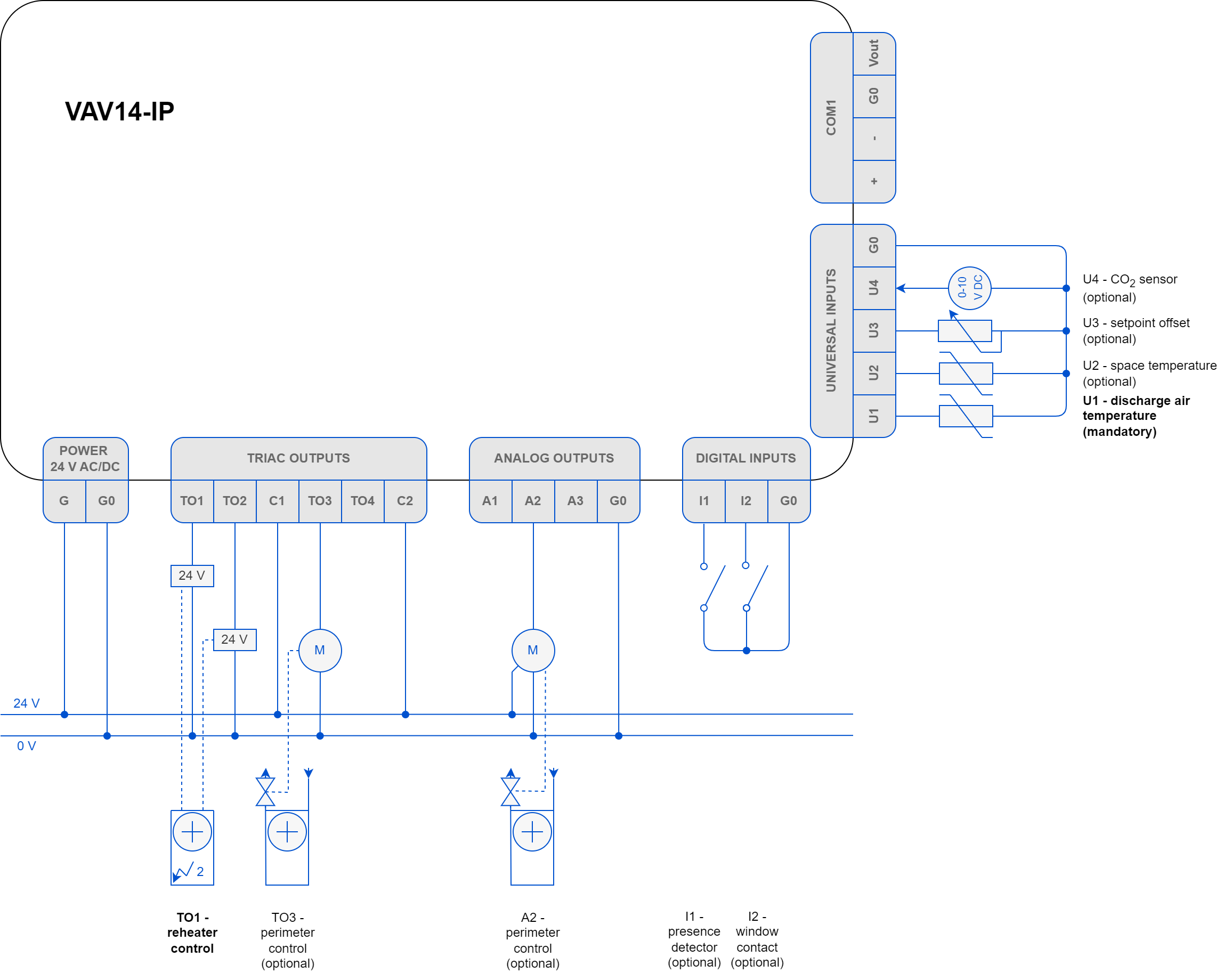
For the application to operate properly, it is required to connect the following elements:
-
Control Point VAV panel or sensors on inputs (space temperature, setpoint offset, CO2 sensor), and
-
DAT sensor located in the supply air duct before VAV.
Optionally, it is possible to connect the presence detector and window contact sensors to minimize energy efficiency loss. To control the reheater and, optionally, perimeter, dedicated triac and analog output are available, as depicted on the diagram above.
Series Fan Powered VAV Cooling with Water Reheater and Optional Perimeter
The series fan powered VAV cooling with water reheater and optional perimeter application requires to configure the following parameters:
-
fan’s control mode (series),
-
reheater’s control type (time proportional – PWM, digital, or floating),
-
(if applicable) perimeter’s control type (time proportional - PWM, on/off).
Configuring of any type of the fan, reheater, or perimeter automatically activates an analog control mode, so it does not require any further configuration.
Other configuration parameters (such as device type – VAV or VVT, damper direction – CW or CCW, default sensor source, type and range or polarity, dual heating function, or heater priority) are available in the Control Point VAV panel or software programming tools (iSMA Configurator/iC Device Manager module/iC Tool).

Series Fan Powered VAV Cooling with up to 2-stage Electric Reheater and Optional Perimeter
The series fan powered VAV cooling with up to 2-stage electric reheater and optional perimeter application requires to configure the following parameters:
-
fan’s control mode (series),
-
reheater’s control type:
-
1-stage reheater: time proportional (PWM), digital (on/off),
-
2-stage reheater: digital (on/off);
-
-
(if applicable) perimeter’s control type (time proportional - PWM, on/off).
Configuring of any type of the fan, reheater, or perimeter automatically activates an analog control mode, so it does not require any further configuration.
Other configuration parameters (such as device type – VAV or VVT, damper direction – CW or CCW, default sensor source, type and range or polarity, dual heating function, or heater priority) are available in the Control Point VAV panel or software programming tools (iSMA Configurator/iC Device Manager module/iC Tool).
For the application to operate properly, it is required to connect the following elements:
-
Control Point VAV panel or sensors on inputs (space temperature, setpoint offset, CO2 sensor), and
-
DAT sensor located in the supply air duct before VAV.
Optionally, it is possible to connect the presence detector and window contact sensors to minimize energy efficiency loss. To control the reheater and, optionally, perimeter, dedicated triac and analog output are available, as depicted on the diagram above.
Parallel Fan Powered VAV Cooling with Water Reheater and Optional Perimeter
The parallel fan powered VAV cooling with water reheater and optional perimeter application requires to configure the following parameters:
-
fan’s control mode (parallel),
-
reheater’s control type (time proportional – PWM, digital, or floating),
-
(if applicable) perimeter’s control type (time proportional - PWM, on/off).
Configuring of any type of the fan, reheater, or perimeter automatically activates an analog control mode, so it does not require any further configuration.
Other configuration parameters (such as device type – VAV or VVT, damper direction – CW or CCW, default sensor source, type and range or polarity, dual heating function, or heater priority) are available in the Control Point VAV panel or software programming tools (iSMA Configurator/iC Device Manager module/iC Tool).
For the application to operate properly, it is required to connect the following elements:
-
Control Point VAV panel or sensors on inputs (space temperature, setpoint offset, CO2 sensor), and
-
DAT sensor located in the supply air duct before VAV.
Optionally, it is possible to connect the presence detector and window contact sensors to minimize energy efficiency loss. To control the reheater and, optionally, perimeter, dedicated triac and analog output are available, as depicted on the diagram above.
Parallel Fan Powered VAV Cooling with up to 2-stage Electric Reheater and Optional Perimeter
The parallel fan powered VAV cooling with up to 2-stage electric reheater and optional perimeter application requires to configure the following parameters:
-
fan’s control mode (parallel),
-
reheater’s control type:
-
1-stage reheater: time proportional (PWM), digital (on/off),
-
2-stage reheater: digital (on/off);
-
-
(if applicable) perimeter’s control type (time proportional - PWM, on/off).
Configuring of any type of the fan, reheater, or perimeter automatically activates an analog control mode, so it does not require any further configuration.
Other configuration parameters (such as device type – VAV or VVT, damper direction – CW or CCW, default sensor source, type and range or polarity, dual heating function, or heater priority) are available in the Control Point VAV panel or software programming tools (iSMA Configurator/iC Device Manager module/iC Tool).

For the application to operate properly, it is required to connect the following elements:
-
Control Point VAV panel or sensors on inputs (space temperature, setpoint offset, CO2 sensor), and
-
DAT sensor located in the supply air duct before VAV.
Optionally, it is possible to connect the presence detector and window contact sensors to minimize energy efficiency loss. To control the reheater and, optionally, perimeter, dedicated triac and analog output are available, as depicted on the diagram above.