Balancing Goals
VAV (Variable Air Volume) balancing is the process of ensuring that a building’s HVAC system delivers the right amount of air to different spaces. The idea of balancing is to find the most efficient operating point of the ventilation system. Proper balancing provides:
-
energy efficiency: minimum consumption of electricity, heating and cooling;
-
user comfort: temperature comfort, noise elimination, air quality.
It establishes a benchmark for the collaboration between AHU and VAV systems. The optimal operating point ensures the minimum amount of air required for the proper functioning of the entire VAV installation.
From a more technically oriented standpoint, there are two main goals that balancing aims to achieve:
-
Obtaining a correct flow from the pressure transducer:
-
if the K-factor VAV box is known, set it in the application and verify the correctness of the flow;
-
if the K-factor of the VAV box is not known, force the damper to open to the maximum flow and set the measured flow in the application – the K-factor will be automatically calculated.
-
-
Damper direction verification:
-
open the damper to the maximum flow – if it is not achieved, change the direction.
-
General aspects of balancing of ventilation VAV systems
-
The first step is to force all VAVs (supply and exhaust separately) to operate at their maximum defined airflow.
-
Set the AHU air efficiency 5-10% higher than the ventilation design (should be consistent with the sum of the VAV air efficiency).
-
The next step is to gradually reduce the AHU efficiency (supply and exhaust separately) and observe the degree of opening of the VAV dampers.
-
Starting from the maximum efficiency of +10% in the AHU, a scenario is created where the VAVs are partially closed. By reducing the air efficiency of the AHU, the VAVs begin to open.
-
The air efficiency of the AHU is lowered until the VAV is almost fully open (85-90%) – usually, this is the VAV at the end of the installation (from the AHU). Calibrate this VAV and recheck.
-
In this way, the optimal operating point for the AHU’s air efficiency is achieved, allowing all other VAVs to self-adjust.
-
Calibrate the rest of the VAV.
VAV Balancing Process
The balancing process involves activities that aim eliminating any discrepancies in airflow adjustment and application calculations:
-
pressure sensor zeroing,
-
setting K-factor,
-
performing maximum airflow calibration,
-
performing minimum airflow calibration.
Based on the user requirements in the area of the balancing process accuracy, all of the above activities can be performed for a full and most advanced balancing outcome or some of them can be omitted. The below diagram shows activities required for the advanced, medium, and basic levels of the balancing accuracy:
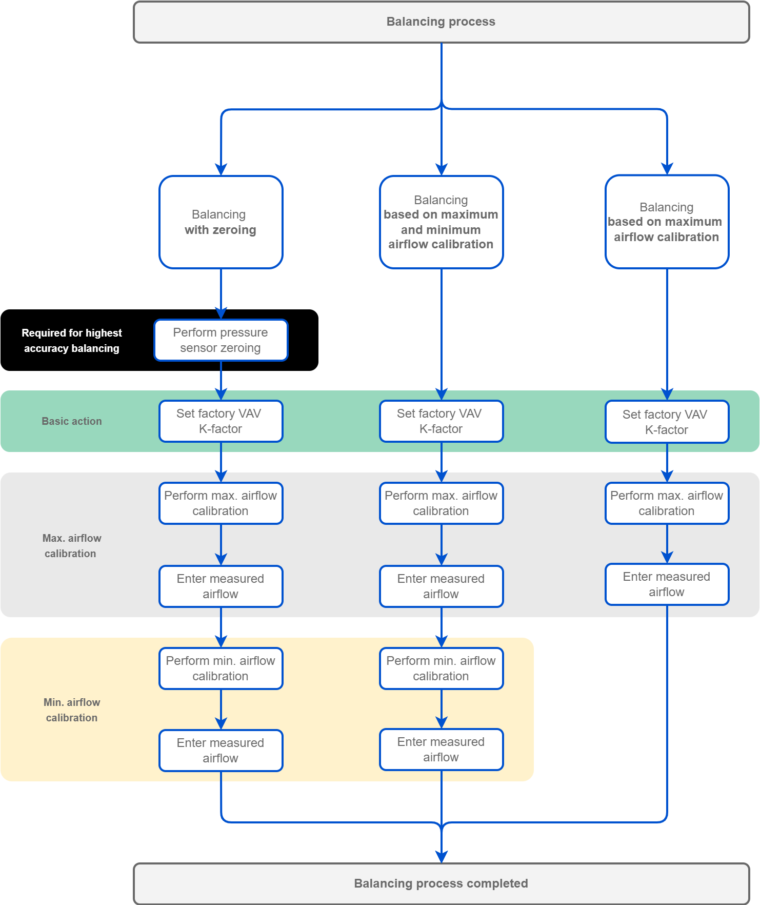
-
If required, the first balancing action is pressure sensor zeroing (this action can be omitted in other variants).
Pressure Sensor Zeroing
Pressure sensor zeroing is a part of the VAV balancing process, which aims at eliminating a constant measurement error of differential pressure on a built-in pressure sensor. The zeroing process involves the following steps:
-
Make sure the differential pressure sensor is disconnected from the measuring cross or other measuring method.
-
Use a flexible hose of an appropriate diameter to connect the two spigots (+ and -).
-
Make sure the hose is well secured and tight to equalize the pressures on both ports.
-
Invoke the zeroing action using one of the methods:
-
using the action in the PressureInput component (iC Tool)
-
in the Balancing tab available in one of the tools (iSMA Configurator, iC Device Manager),
-
writing a value to the PressureZeroing variable (BACnet object: BV13, Modbus address: 13),
-
from the Control Point VAV panel.
-
-
Detach the hose.
-
Restore the normal connection of the sensor to the measuring cross or other target circuit, pay attention to the polarity.
-
Then, the common and mandatory action for all variants, setting the K-factor.
Note
The K-factor is provided by the manufacturer of the VAV box. If for any reason it is unavailable, it is recommended to use a default K-factor from the VAV application (100 l/s /1000 cfm).
-
Next action is the maximum airflow calibration. Performing it is the necessary minimum of the balancing process.
-
If required, the minimum airflow calibration is the last step of the balancing process.
Tools
Balancing can be performed using one of the iC Tools provided for this purpose: