The device is equipped with an opto-isolated RS485 base port, which allows connecting the device to the BMS in order to communicate with other devices in the network. The optional controller version has an extension of a second RS 485 port. All rules are the same as in the base port. The way of proper bus cable connection is shown in the figure below.
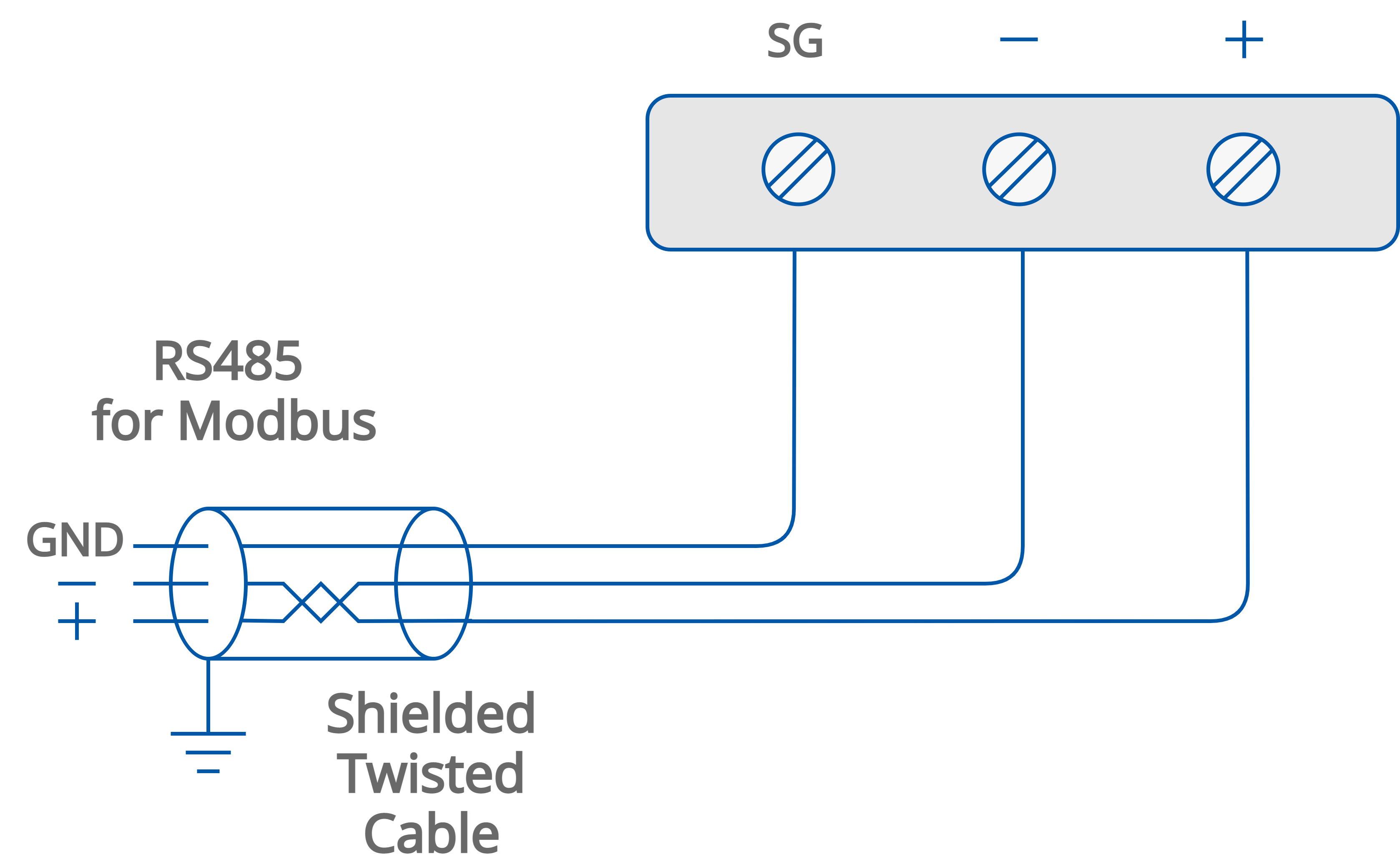
The RS485 communication bus connection
RS485 Grounding and Shielding
The device can be exposed to electromagnetic environment. The electromagnetic radiation can induce electrical noise into both power and signal lines, as well as direct radiation into the device causing negative effects to the device functioning. Appropriate grounding, shielding and the other protective steps should be taken at the installation stage to prevent undesirable effects. The preventions include making control cabinets grounding, cables shield grounding, using protective elements for electromagnetic switching devices, using correct wiring as well as appropriate cable types selection and cable cross-sections.
RS485 Network Termination and Biasing
The transmission line often creates communication problems. These problems include reflections and signal attenuation.
To eliminate the presence of reflections at the ends of the bus cable, it must be terminated at both ends with a resistor across the line. The resistor value has to be the same as a characteristic impedance of the bus cable. Both ends must be terminated since the direction of propagation is bidirectional. In case of an RS485 twisted pair cable, the termination is typically 120 Ω.
In the iSMA-B-MAC36NL version there is a built-in 3-position switch on the back side of the device (access after removing the back cover), which is dedicated to connecting termination resistor and/or biasing resistors. In the iSMA-B-MAC36NL-RS version a 3-position switch is installed below a terminal connector, as shown in the figure below on the right side.
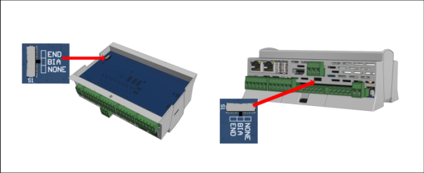
Switch for termination and biasing for the base (on the left) and optional extension port (on the right)
|
Switch position |
Biasing |
Termination 120 Ω + Biasing |
|---|---|---|
|
END |
OFF |
ON |
|
BIA |
ON |
OFF |
|
NONE |
OFF |
OFF |
Switch for termination and biasing
If the switch is in the END position, it connects the termination resistor 120 Ω and biasing resistors 680 Ω (pull-down to ground SG and pull-up to +5 V DC) to the RS485 bus.
Instead of using additional resistors, the termination and biasing can easily be done by a simple switch activation.
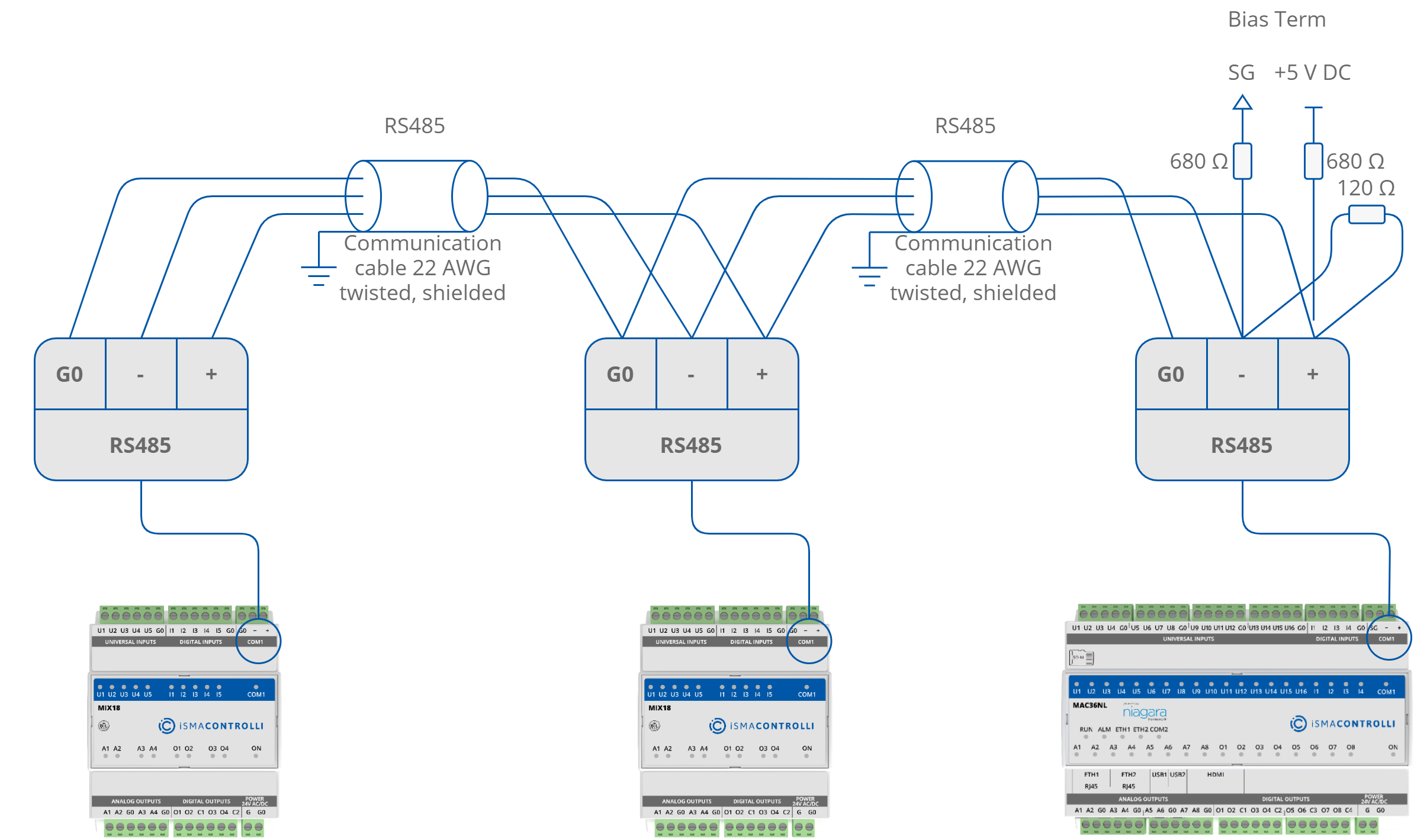
RS485 network termination and biasing
If the switch is in the BIA position, it connects the biasing resistors 680 Ω (pull-down to ground SG and pull-up to +5 V DC) to the RS485 bus. The biasing is added to the RS485 bus in order to reduce communication failures.
WARNING! Only one single device on the network can have biasing resistors connected. Connecting biasing resistors on two or more devices on a single RS485 bus will take the opposite effect–increase the number of communication problems.
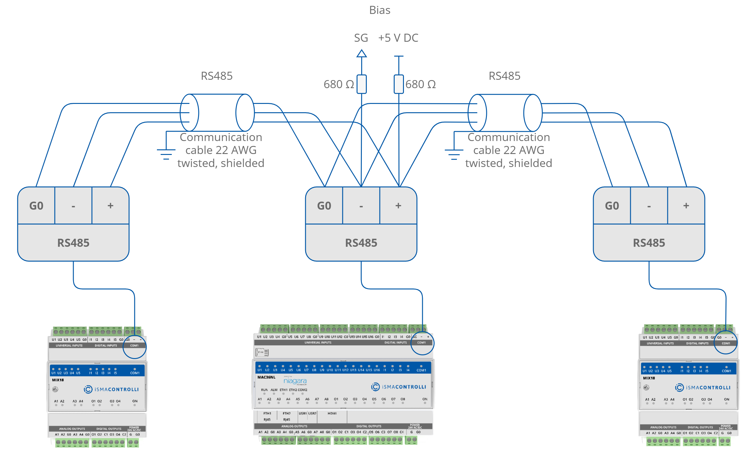
RS485 network biasing