Applicable to OS V1.10
The LightSensor component is a network point class component designed to service the DALI-2 input device instance of type 4 (light intensity measurement). The component works in an event-driven mode (the Out value changes instantly after an event), but can be set to work in a standard polling mode.
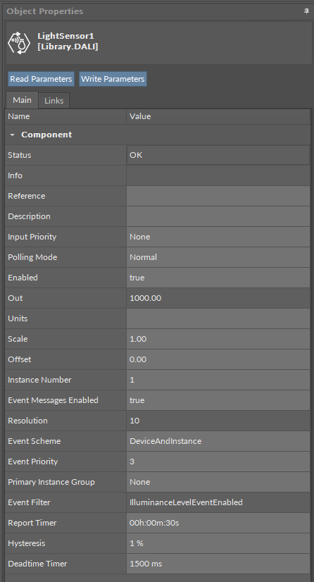
The LightSensor component has the following slots:
-
Status: indicates the current status of the component; if the component works properly, its status is OK. The component becomes Disabled, once the Enabled slot is in false. The component's status is Fault, once the component is not located under the InputDevice device. If there is no response from the device addressed in the InputDevice component, the component goes into the Down status,
-
Available information: Disabled, Fault, Down, OK;
-
-
Info: provides a detailed information about non-OK statuses of the component;
-
Available information:
-
Bad request (status Down): occurs when point could not be polled successfully, most likely because its parameters are incorrect (e.g., a short address set in the host InputDevice component is unavailable);
-
Request timed out (status Down): occurs when the point cannot be polled for some time;
-
Waiting for network reconfiguration… (status Down): caused by disabling/enabling the point, changing its parameters, or by changes in networks – in this case the Down status is only temporary and should switch back to OK in a couple of seconds;
-
Incorrect placement - must be placed under Device (status Fault): occurs if the point is placed in a different location than under Device in a DALI network; for example, when the network point class component is placed in the Applications container instead of the Networks;
-
Incorrect placement - must be placed under compatible communication protocol (status Fault): occurs if the point is placed under network different than DALI;
-
Incorrect configuration (status Fault): the short address is not defined;
-
Device disabled (status Disabled): the Enabled slot in the host InputDevice component is set to false;
-
Point disabled (status Disabled): the Enabled slot in the component is set to false;
-
-
The Info is a numerical slot, which displays a correlated text information:
|
Numerical value |
Displayed information |
|---|---|
|
0 |
No information displayed in the Info slot |
|
1 |
Bad request |
|
2 |
Request timed out |
|
3 |
Waiting for network reconfiguration |
|
4 |
Incorrect placement - must be placed under Device |
|
5 |
Incorrect placement - must be placed under compatible communication protocol |
|
6 |
Incorrect configuration |
|
7 |
Device disabled |
|
8 |
Point disabled |
-
Reference: a special slot allowing to connect network point class components with Data Point class components. It allows to transfer the Out slot value along with the component's status.
Note: Reference links from Data Points to network points also transfer values in the opposite direction, in a link-back-from process: having received a value by the Reference link, the network point transfers it back to the Data Point to whichever input priority from 1 to 16 is set in the network point.
-
Description: an additional detailed information about a component that may be freely described by the user; the description may contain individual coding, defined in the user's system documentation, device's location, or any other information the user finds applicable.
Note: The description is effectively added only if the point allows it–the description is not added internally in the controller for the remote point, but it is sent directly to the point.
-
Input Priority: allows to indicate the input number in the Data Point, which the network point class component's output value is sent to, in case the network point detects the change on its Out slot; none priority is set by default.
-
Available settings: none, 1-16.
-
-
Polling Mode: allows to set the frequency of sending polling requests for the point's value to remote devices—the polling mode is automatically set to normal;
-
Available settings: fast, normal, slow;
-
-
Enabled: change of the slot's value enables or disables the component;
-
Available settings: true (enabled), false (disabled);
-
Note: If the Enabled slot is in false (meaning the component is disabled), the Status slot becomes Disabled;
-
Out: an actual value of a remote device;
Note: If the Out slot has a value of 255, it means that a remote device is broken or not powered up. If the component's Status is fault (e.g., the Instance Number slot is empty), the Out value is null.
-
Units: defines a unit of the Out slot value; no unit is set by default;
-
Scale: sets a fixed scaling factor for an output linearization; the written value is calculated according to the inverse linear function formula (x=(y-b)/a), and the calculated value is read to the Out slot according to the linear function (y=ax+b); the Scale slot sets the a value of the formula; incorrect scaling of the results in the calculated value (exceeding the available range for the device, e.g., 0-10 V), results in indicating a different value on the input and on the Out slot. If the scaling is correct, the values are identical;
-
Offset: sets a fixed offset value to the output value; the value is calculated according to the inverse linear function formula (x=(y-b)/a) and read to the Out slot according to the linear function (y=ax+b); the Offset slot sets the b value of the formula; incorrect scaling of the results in the calculated value (exceeding the available range for the device, e.g., 0-10 V), results in indicating a different value on the input and on the Out slot. If the scaling is correct, the values are identical;
-
Instance Number: allows to enter an instance address of the point in the DALI-2 input device;
Note: Instance address in this slot is not written to the device itself, only in the application controller’s logic. The communication with the remote device will be sustained if the DALI short address in the InputDevice component and the instance address in the Instance Number slot are identical to the remote device’s.
-
Event Messages Enabled: allows to enable or disable an asynchronous updating of the Out value based on events' occurrence;
Note: If disabled, the component work in the cyclical polling mode.
-
Resolution: shows a resolution of the point’s value;
Note: In the event-driven mode, the resolution is limited to 10 bits. In the polling mode, the resolution is not limited.
-
Event Scheme: allows to define which event addressing scheme is applied to this instance for event handling;
-
Available settings: Instance (0), Device (1), DeviceAndInstance (2), DeviceGroup (3), InstanceGroup (4);
-
|
Event scheme |
Description |
|---|---|
|
Instance |
Addressing using an instance type and number |
|
Device |
Addressing using a short address and instance type |
|
DeviceAndInstance (default) |
Addressing using a short address and instance number |
|
DeviceGroup |
Addressing using a device group and instance type |
|
InstanceGroup |
Addressing using an instance group and type |
Note: In event schemes other than DeviceAndInstance, multiple instances can generate events that are captured within the same network point, allowing an event consolidation across instances of the same type or group.
-
Event Priority: allows to set a priority level for events generated by this point;
-
Available settings:
-
-
Primary Instance Group: (applicable only when the InstanceGroup event scheme is used) allows to define a primary instance group used for organizing the point within system structures;
-
Available settings: none (-1), Group0 (0)–Group31 (31);
-
-
Event Filter: displays an event filter applied to the point, determining which events are processed or ignored;
-
Available information: IlluminanceLevelEventEnabled;
-
-
Report Timer: allows to define a report interval for the point in seconds. The report timer makes the instance generate a ‘repeat’ trigger event periodically even if the input value has not changed, ensuring regular updates to the system for monitoring;
-
Hysteresis: allows to define a percentage hysteresis band applied to lighting level changes to avoid generating events on minor fluctuations. Each time the input value exceeds the calculated hysteresis band, a new event is generated, and the band recalculates dynamically according to the measured value;
Note: If set to 0%, the device will trigger events solely based on the Report Timer.
-
Deadtime Timer: allows to define a time period (in milliseconds) after sending an event during which no new events will be sent, even if the input changes. The value is configured in increments of 50 ms.