Direct interaction with the Touch Point 2.0 device is possible via user interface (buttons and display, if available) by default. The panel can be activated or inactivated using the following parameter or in the iSMA Configurator:
DEVICE_CONFIGURATION, bit 11: PANEL_OFF
-
Modbus register: 40205;
-
BACnet object: BO9, property: Present Value.
Display
Warning!
This section applies to the Touch Point 2.0, Touch Point ONE 2.0, and Touch Point VAV 2.0 series. The Touch Point L&B 2.0 and Touch Point Network Sensor 2.0 series are not equipped with a display.
The display functions can be activated or inactivated using the following parameter or in the iSMA Configurator:
DEVICE_CONFIGURATION, bit 3: LCD_BACKLIGHT_ACTIVE
-
Modbus register: 40205;
-
BACnet object: BO3, property: Present Value.
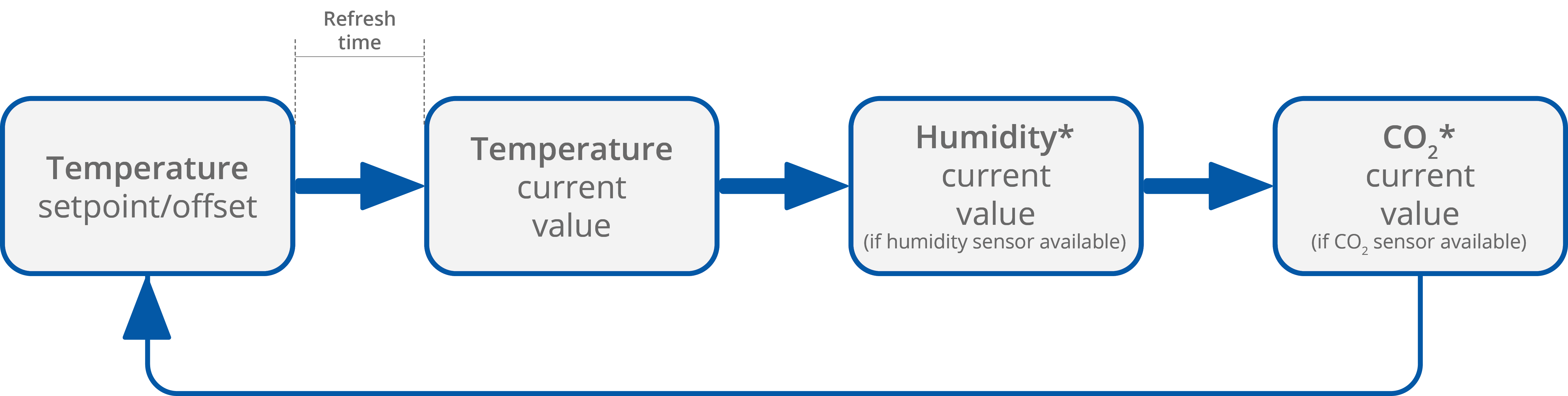
During a normal operation, the display shows measured values for all sensors available in the panel and a temperature setpoint (if available), with parameter’s shortcut name and a proper unit.
The display configuration parameters include the following (these functions can be edited directly in the parameters or in the iSMA Configurator):
REFRESH_TIME: sets the duration of the display time of particular parameters. When the refreshing time elapses, the next parameter is displayed according to the sequence of parameters display. The default value is 5 seconds (each parameter is displayed for 5 seconds). The maximum refreshing time is 60 seconds.
-
Modbus register: 40217;
-
BACnet object: AO13, property: Present Value;
TEMPERATURE_CONFIGURATION: allows to configure the temperature sensor with two bits:
-
ACTIVE, bit 0: activates or deactivates the sensor;
-
Modbus register: 40316;
-
BACnet object: AI4, property: Out Of Service;
-
-
THIRD_POINT_ACTIVE, bit 4: enables or disables decimal values in the sensor;
-
Modbus register: 40316;
-
BACnet object: AI4, property: 4202;
-
|
Bit |
Name |
0 |
1 |
|---|---|---|---|
|
0 |
ACTIVE |
Inactive |
Active (default) |
|
4 |
THIRD_POINT_ACTIVE |
No decimal |
Decimal (default) |
HUMIDITY_CONFIGURATION: allows to configure the humidity sensor with two bits:
-
ACTIVE, bit 0: activates or deactivates the sensor;
-
Modbus register: 40317;
-
BACnet object: AI5, property: Out Of Service;
-
-
THIRD_POINT_ACTIVE, bit 4: enables or disables decimal values in the sensor;
-
Modbus register: 40317;
-
BACnet object: AI5, property: 4202;
-
|
Bit |
Name |
0 |
1 |
|---|---|---|---|
|
0 |
ACTIVE |
Inactive |
Active (default) |
|
4 |
THIRD_POINT_ACTIVE |
No decimal |
Decimal (default) |
CO2_CONFIGURATION: allows to activate or deactivate the CO2 sensor:
-
ACTIVE, bit 0: activates or deactivates the sensor;
-
Modbus register: 40318;
-
BACnet object: AI6, property: Out Of Service;
-
|
Bit |
Name |
0 |
1 |
|---|---|---|---|
|
0 |
ACTIVE |
Inactive |
Active (default) |
CO2 sensors installed in Touch Point 2.0 panels are subject to an automatic sensor calibration system. Learn more: Touch Point 2.0 Hardware user manual.
SETPOINT_CONFIGURATION: allows to configure the temperature setpoint with five bits:
-
VISIBLE, bit 0: enables or disables the temperature setpoint to be visible on the panel's display;
-
Modbus register: 41513;
-
BACnet object: AV56, property: Out Of Service;
-
-
EDITABLE, bit 1: enables or disables editing of the temperature setpoint locally from the panel;
-
Modbus register: 41513;
-
BACnet object: AV56, property: 4200;
-
-
OPERATING_MODE, bit 2: allows to set the operating mode of the temperature setpoint configuration;
-
Modbus register: 41513;
-
BACnet object: BO55, property: Out Of Service;
-
-
SETPOINT_DISPLAY, bit 3: allows to configure the temperature setpoint display;
-
Modbus register: 41513;
-
BACnet object: BO56, property: Out Of Service;
-
-
THIRD_POINT_ACTIVE, bit 4: enables or disables decimal values in the temperature setpoint;
-
Modbus register: 41513;
-
BACnet object: AV56, property: 4202;
-
|
Bit |
Name |
0 |
1 |
|---|---|---|---|
|
0 |
Visible |
Not visible |
Visible (default) |
|
1 |
Editable |
Not editable |
Editable (default) |
|
2 |
Operating mode |
Changing offset |
Changing setpoint (default) |
|
3 |
Setpoint display |
Show/change offset (OFFSET_SETPOINT value) |
Show/change effective setpoint (EFFECTIVE_SETPOINT value) |
|
4 |
ThirdPointActive |
No decimal |
Decimal (default) |
Display Brightness
Display brightness switches between three illumination modes in time:
-
active mode;
-
idle mode;
-
standby mode.
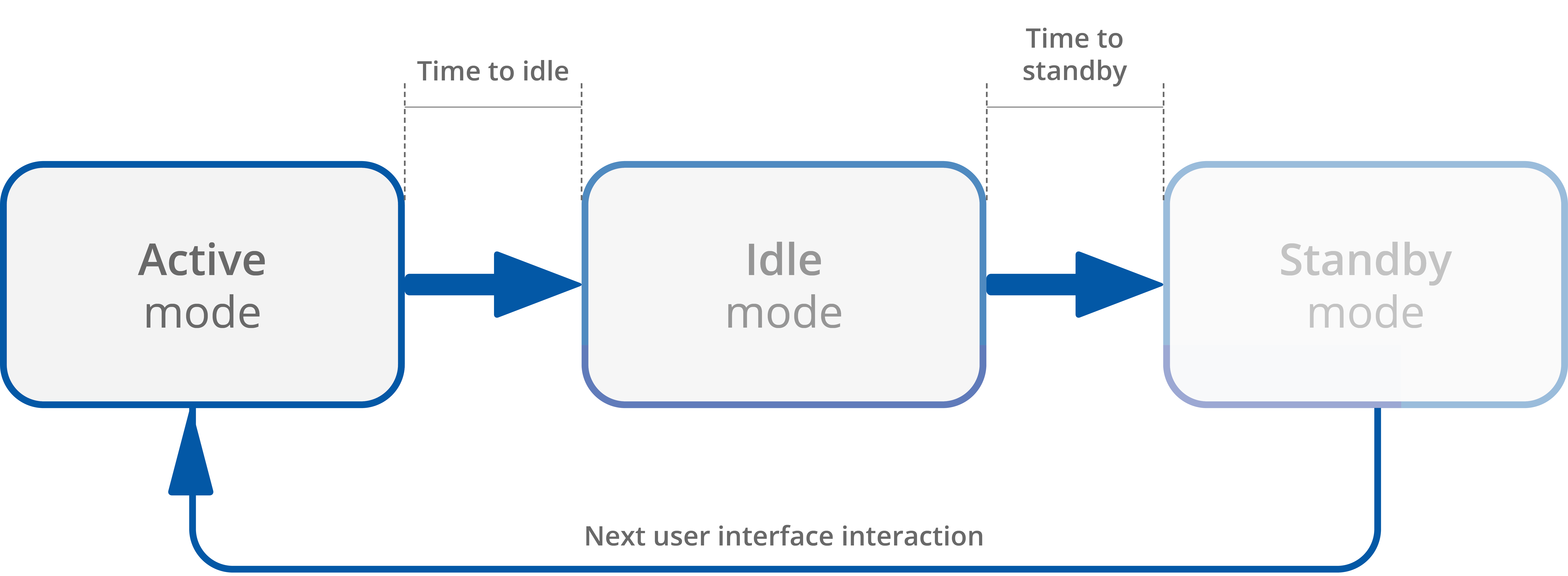
Active Mode Settings
BACKLIGHT_LCD_ACTIVE: contains a value of the LCD display brightness in the active mode (expressed in %). The default value is 60%.
-
Modbus register: 40207;
-
BACnet object: AO3, property: Present Value;
BACKLIGHT_LCD_TIME_TO_IDLE: allows to set the time, after which the LCD display goes from the active mode to idle (expressed in seconds). The default value is 10 seconds.
-
Modbus register: 40210;
-
BACnet object: AO6, property: Present Value;
Idle Mode Settings
BACKLIGHT_LCD_IDLE: contains a value of the LCD display brightness in the idle mode (expressed in %). The default value is 40%.
-
Modbus register: 40208;
-
BACnet object: AO4, property: Present Value.
BACKLIGHT_LCD_TIME_TO_STANDBY: allows to set the time, after which the LCD display goes from the idle mode to standby (expressed in seconds). The default value is 5 seconds.
-
Modbus register: 40211;
-
BACnet object: AO7, property: Present Value.
Standby Mode Settings
BACKLIGHT_LCD_STANDBY: contains a value of the LCD display brightness in the standby mode (expressed in %). The default value is 0%.
-
Modbus register: 40209;
-
BACnet object: AO5, property: Present Value.
The panel stays in the standby mode until next user interface interaction.
Current Display Brightness
BACKLIGHT_LCD: contains a current display illumination value.
-
Modbus register: 30201;
-
BACnet object: AI1, property: Present Value.
Keypad
Warning!
This section applies to the Touch Point 2.0, Touch Point ONE 2.0, Touch Point VAV 2.0, and Touch Point L&B 2.0 series. The Touch Point Network Sensor 2.0 series is not equipped with a display or any control buttons.
A front panel of the panel is equipped with LEDs that illuminate buttons and other symbols available on the panel's keypad. The LEDs can be activated or inactivated using the following parameter or in the iSMA Configurator:
DEVICE_CONFIGURATION, bit 4: KEYPAD_BACKLIGHT_ACTIVE
-
Modbus register: 40205;
-
BACnet object: BO4, property: Present Value.
Keypad brightness switches between three illumination modes in time:
-
active mode;
-
idle mode;
-
standby mode.
Keypad Brightness
Active Mode Settings
BACKLIGHT_KEYPAD_ACTIVE: contains a value of the LCD display brightness in the active mode (expressed in %). The default value is 60%.
-
Modbus register: 40212;
-
BACnet object: AO8, property: Present Value;
BACKLIGHT_KEYPAD_TIME_TO_IDLE: allows to set the time, after which the LCD display goes from the active mode to idle (expressed in seconds). The default value is 10 seconds.
-
Modbus register: 40215;
-
BACnet object: AO11, property: Present Value;
Idle Mode Settings
BACKLIGHT_KEYPAD_IDLE: contains a value of the LCD display brightness in the idle mode (expressed in %). The default value is 40%.
-
Modbus register: 40213;
-
BACnet object: AO9, property: Present Value.
BACKLIGHT_KEYPAD_TIME_TO_STANDBY: allows to set the time, after which the LCD display goes from the idle mode to standby (expressed in seconds). The default value is 5 seconds.
-
Modbus register: 40216;
-
BACnet object: AO12, property: Present Value.
Standby Mode Settings
BACKLIGHT_KEYPAD_STANDBY: contains a value of the LCD display brightness in the standby mode (expressed in %). The default value is 0%.
-
Modbus register: 40214;
-
BACnet object: AO10, property: Present Value.
The panel stays in the standby mode until next user interface interaction.
Current Display Brightness
BACKLIGHT_KEYPAD: contains a current display illumination value.
-
Modbus register: 30202;
-
BACnet object: AI2, property: Present Value.
Touch Panel
The Touch Point 2.0 panels are equipped with a touch panel with various combinations of buttons for occupancy, temperature (+/-), fan (+/-) control, and generic buttons. The touch panel buttons can be activated or inactivated using the following parameter or in the iSMA Configurator:
DEVICE_CONFIGURATION, bit 12: KEYPAD_OFF
-
Modbus register: 40205;
-
BACnet object: BO10, property: Present Value.
Each available button operates in two modes:
-
short press: minimal touch time: 70 ms, maximal touch time: 400 ms;
-
long press: minimal touch time: 400 ms, maximal touch time: 11 s.
Functionality assigned to a given button can limit mentioned operation modes to any combination of the two.
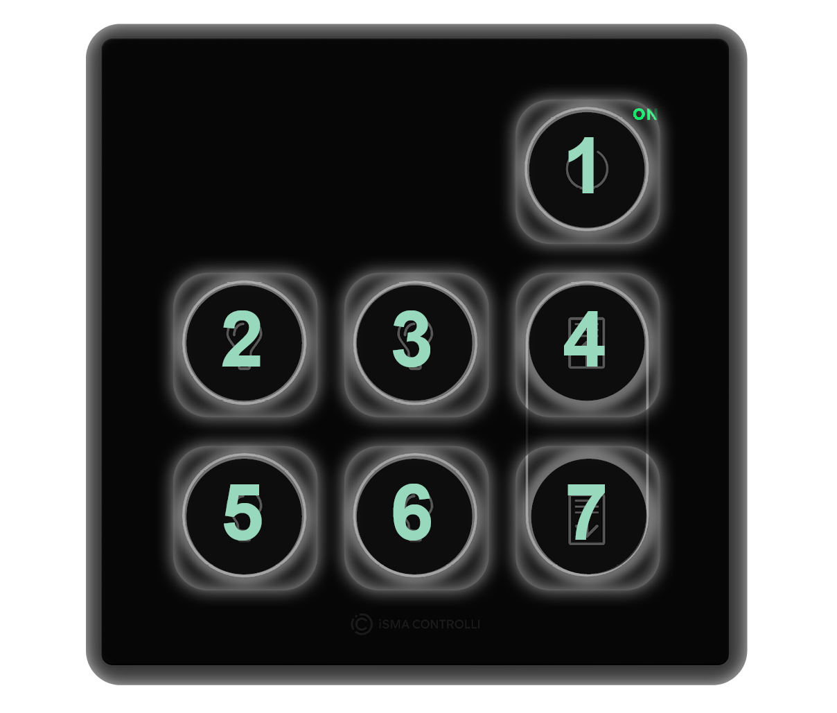
Generic Buttons
The Touch Point ONE 2.0 and Touch Point Light&Blind 2.0 series are equipped with generic buttons, which do not have any default logic assigned to their operation—first, it is required to program them in the controller. The following parameters are applicable to generic buttons configuration.
Generic buttons distribution
Various types of panels can be equipped with 2 to 7 of generic buttons:
-
Touch Point 4L1B 2.0: 7 generic buttons,
-
Touch Point ONE 2.0: 6 generic buttons (nos. 2, 3, 4, 5, 6, 7)
-
Touch Point 4L 2.0: 5 generic buttons (nos. 1, 2, 4, 5, 7),
-
Touch Point ONE 2L/1B 2.0: 2 generic buttons (nos. 4, 7).
Regardless of the above configurations, generic buttons are always numbered the same for programming:
GENERIC_BUTTON_N_MODE: (N - a number of a generic button, 1-7) defines a generic button’s behavior:
|
Value |
Mode |
Description |
|---|---|---|
|
1 |
Disabled |
Disables a generic button functionality (except for LED BMS control) |
|
2 |
Blocked |
Blocks a generic button control from a touch sensor input |
|
3 |
Bistable |
Generic button works as a standard bistable switch |
|
4 |
Monostable - normally off |
Generic button works as a standard monostable NO switch |
|
5 |
Monostable - normally on |
Generic button works as a standard monostable NC switch |
-
Modbus registers: 41342-41348;
-
BACnet object: MSV21-27, property: Present Value.
GENERIC_BUTTON_STATES: receives a state (on/off) of 1-7 generic buttons:
|
Value |
State |
Description |
|---|---|---|
|
0 |
Off |
Low logic generic button state |
|
1 |
On |
High logic generic button state |
-
Modbus register: 41349, bits 0-6;
-
BACnet object: BV56-62, property: Present Value.
GENERIC_BUTTON_LED_MODES: defines a behavior of a generic button LED, if assigned:
|
Value |
State |
Description |
|---|---|---|
|
0 |
LED BMS mode |
LED state follows the state set in LED BMS state parameter |
|
1 |
LED local mode |
LED state follows the button state |
-
Modbus register: 41350, bits 0-6;
-
BACnet object: BV63-69, property: Present Value.
GENERIC_BUTTON_LED_BMS_STATES: receives a LED BMS state set on a generic button LED if LED mode is set to BMS mode:
|
Value |
State |
Description |
|---|---|---|
|
0 |
Off |
Additional LED is off |
|
1 |
On |
Additional LED is on |
-
Modbus registers: 41352, bits 0-6;
-
BACnet object: BV70-76, property: Present Value.
Navigation LED
Warning!
This section applies to all Touch Point 2.0 series: Touch Point 2.0, Touch Point ONE 2.0, Touch Point VAV 2.0, Touch Point L&B 2.0, and Touch Point Network Sensor 2.0 series.
The Touch Point 2.0 panels are equipped with a navigation LED, which allows to locate the panel in the dark. The navigation LED can be configured using the following parameters or in the iSMA Configurator:
NAVIGATIONAL_LED_MODE: allows to set a mode of the navigational LED according to the table below:
|
Modbus value |
BACnet value |
Mode if active |
|---|---|---|
|
0 |
1 |
Off |
|
1 |
2 |
On (default) |
|
2 |
3 |
Active on idle and standby modes |
|
3 |
4 |
Active on idle mode only |
|
4 |
5 |
Active on standby mode only |
|
5 |
6 |
BMS mode |
-
Modbus register: 30231;
-
BACnet object: MSV18, property: Present Value;
NAVIGATIONAL_LED_BRIGHTNESS: allows to set the navigational LED brightness. In the range of 0-100%, the default value is 100%;
-
Modbus register: 30232;
-
BACnet object: AO39, property: Present Value;
NAVIGATIONAL_LED_RED: allows to set a red component intensity is the navigational LED. In the range of 0-100%, the default value is 100%;
-
Modbus register: 30233;
-
BACnet object: AO40, property: Present Value;
NAVIGATIONAL_LED_GREEN: allows to set a green component intensity is the navigational LED. In the range of 0-100%, the default value is 100%;
-
Modbus register: 30234;
-
BACnet object: AO41, property: Present Value;
NAVIGATIONAL_LED_BLUE: allows to set a blue component intensity is the navigational LED. In the range of 0-100%, the default value is 100%;
-
Modbus register: 30235;
-
BACnet object: AO42, property: Present Value.
Buzzer
The Touch Point 2.0 panels are equipped with a buzzer, which informs about a detected touch with a short sound. The buzzer also provides a CO2 alarm function, which emits a sound once the CO2 level exceeds a set alarm value. The alarm can be confirmed and muted by pressing any button. The buzzer can be activated or inactivated using the following parameter or in the iSMA Configurator:
DEVICE_CONFIGURATION, bit 0: BEEPER_ACTIVE
-
Modbus register: 40205;
-
BACnet object: BO0, property: Present Value.
The buzzer can be configured using the following parameters or in the iSMA Configurator:
BUZZER_VOLUME: allows to set a buzzer volume (expressed in %). The default value is 50%.
-
Modbus register: 40323;
-
BACnet object: AO43, property: Present Value;
BUZZER_TONE: allows to select a buzzer tone (discrete, loud, classic, retro).
-
Modbus register: 40324;
-
BACnet object: MSV20, property: Present Value.