The Touch Point 2.0 panels equipped with generic buttons are the Touch Point ONE 2.0 and Touch Point Light&Blind 2.0 series. These two series of Touch Point 2.0 panels are dedicated to facilitate light and blind control with Modbus/BACnet-enabled controllers. They are recommended to be integrated with the ZAC24-IP-D, the DALI-2 controller driven by the nano EDGE ENGINE.
Generic buttons can be freely programmed as they do not have any default logic assigned to their operation. They can be configured to one of the following modes of operation:
-
monostable - normally on,
-
monostable - normally off,
-
bistable,
-
disable,
-
blocked.
The following section describes steps to connect the ZAC24-IP-D controller with a compatible Touch Point 2.0 panel.
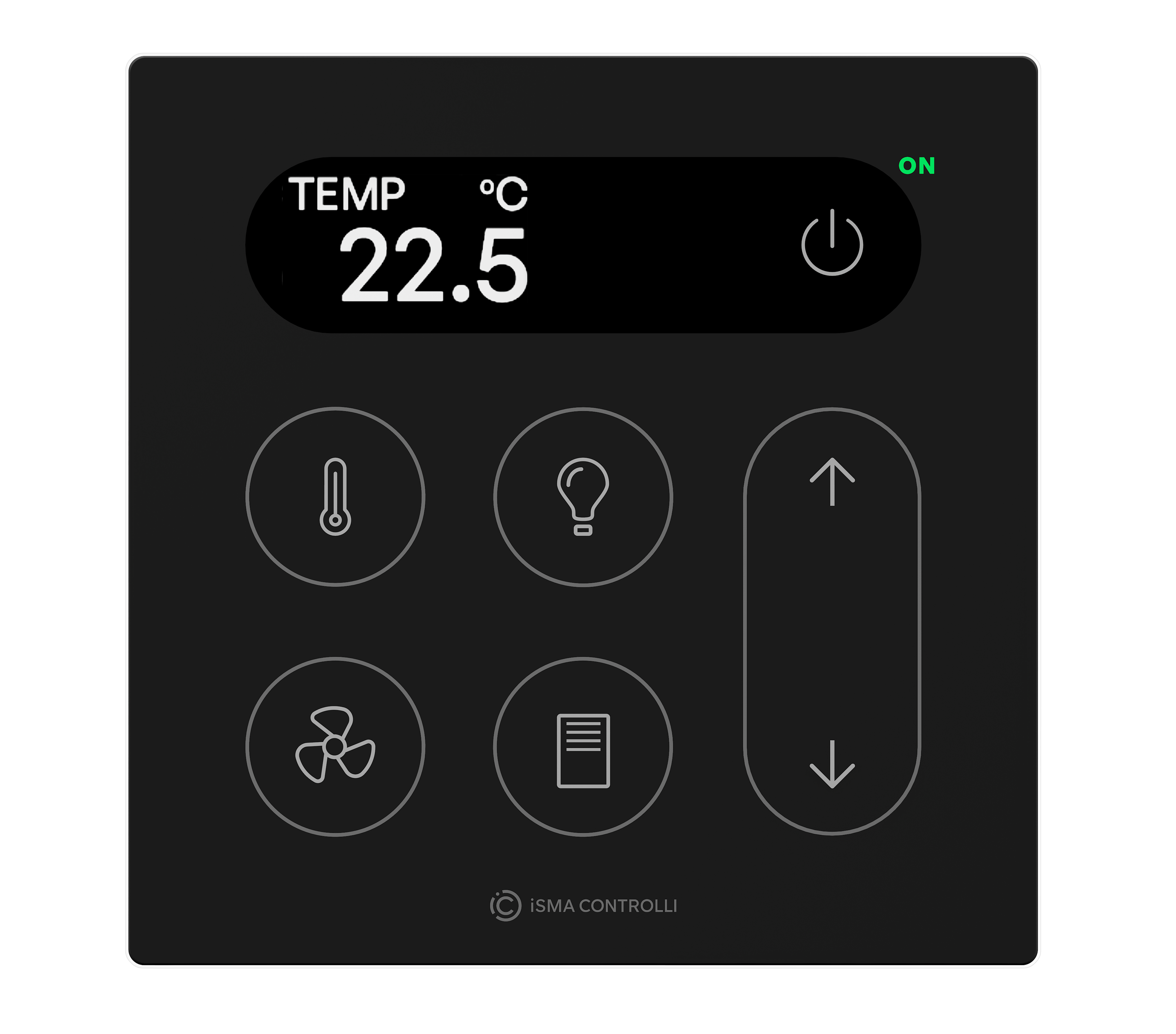
Touch Point ONE 2.0
The Touch Point ONE 2.0 panel is programmed with the use of the TpOneControlLogic component from the nano EDGE ENGINE’s ComfortControl library. The component offers a pre-configured logic for the generic buttons functional distribution on the Touch Point ONE 2.0 touch panel.
Step 1: Connection
Make sure that the Touch Point ONE 2.0 panel and the controller are powered and correctly connected to the network.
In the nano EDGE ENGINE software tool (iC Tool/nE2 Link module), go to the Networks container, Modbus network (Modbus is recommended).
Recommended parameters
It is recommended to set the polling mode to fast with the fast mode parameter set to 100 ms.
Add devices to the network and address them properly.
Step 2: Points
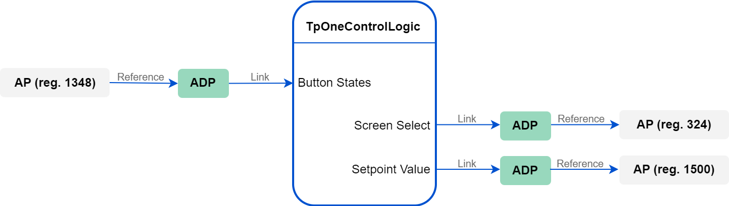
For a correct connection with the TpOneControlLogic component, it is required to add the following three network points to the Modbus device:
-
AnalogPoint for the generic buttons state register (Address slot: 1348),
-
AnalogPoint for the screen select mode register (Address slot: 324),
-
AnalogPoint for the temperature setpoint register (Address slot: 1500).
Step 3: TpOneControlLogic component
Add the TpOneControlLogic component (from the ComfortControl library) to the application.
Recommended parameters
It is recommended to add the TpOneControlLogic component to the application, which scan time is set to 100 ms. Slower applications may hinder a proper operation of the component.
Step 4: Data Points and Linking
Add three AnalogDataPoints to the same application, where the TpOneControlLogic component has been added.
Create the following Reference Link from the Reference slot in the network point to the Reference slot in the Data Point:
-
AnalogPoint for the generic buttons state to the first AnalogDataPoint.
Create the following Reference Links from the Reference slot in the Data Point to the Reference slot in the network point:
-
AnalogDataPoint to the AnalogPoint for the screen select mode,
-
AnalogDataPoint to the AnalogPoint for the temperature setpoint.
Create the following links with the TpOneControlLogic component:
-
(incoming) AnalogDataPoint’s (referenced to generic buttons register) Out slot to the Button States slot,
-
(outgoing) the Screen Select slot to the In slot of the AnalogDataPoint referenced to the screen select mode register,
-
(outgoing) the Setpoint Value slot to the In slot of the AnalogDataPoint referenced to the temperature setpoint register.
If required, configure the rest of the TpOneControlLogic component slots as necessary.
Light dimming
To control the light with dimming, use the LightOnOffDimming2Switch component available in the LightControl library.
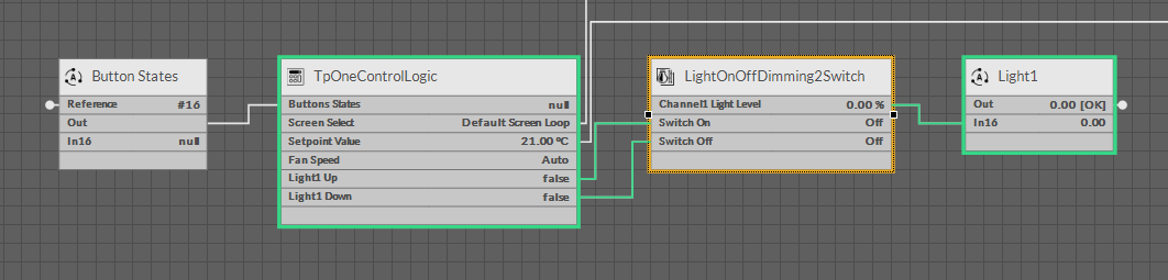
Add the LightOnOffDimming2Switch component to the application. Link the Light Up and Light Down slots of the TpOneControlLogic component, corresponding to the generic button, with the Switch On and Switch Off slots of the LightOnOffDimming2Switch component. Then, link the Channel1 Light Level slot of the LightOnOffDimming2Switch with the input slot of the AnalogDataPoint controlling the light.
Touch Point ONE 2L/1B 2.0 and Touch Point Light&Blind 2.0
The Touch Point ONE 2L/1B 2.0 and Touch Point Light&Blind 2.0 panels are equipped with generic buttons, which can be programmed with the use of the GENERIC_BUTTON_STATES register.
Step 1: Connection
Make sure that the Touch Point ONE 2L/1B 2.0/Touch Point Light&Blind 2.0 panel and controller are powered and correctly connected to the network.
In the nano EDGE ENGINE software tool (iC Tool/nE2 Link module), go to the Networks container, Modbus network (Modbus is recommended).
Recommended parameters
It is recommended to set the polling mode to fast with the fast mode parameter set to 100 ms.
Add devices to the network and address them properly.
Step 2: Point
Add the following the network point to the Modbus device:
-
AnalogPoint for the generic buttons state register (Address slot: 1348).
Step 3: Data Point and Linking
Add the AnalogDataPoint to the application.
Recommended parameters
It is recommended to add the Data Point to the application, which scan time is set to 100 ms. Slower applications may hinder a proper data transmission between the panel and the controller.
Create the Reference Link from the AnalogPoint for the generic buttons state to the AnalogDataPoint (from the Reference slot in the network point to the Reference slot in the Data Point).
Step 4: Bits
Add the Numeric2Binary component to the same application, where the AnalogDataPoint has been added.
Link the AnalogDataPoint’s Out slot to the In slot of the Numeric2Binary component. Use the Numeric2Binary bits slots to link the data from the corresponding generic button in the application (for example, to the components from the LightControl library).
The GENERIC_BUTTON_STATES register contains information about generic buttons states on bits 0-6:
|
Button no. |
Bit |
|---|---|
|
1 |
0 |
|
2 |
1 |
|
3 |
2 |
|
4 |
3 |
|
5 |
4 |
|
6 |
5 |
|
7 |
6 |
Light dimming
To control the light with dimming, use the LightOnOffDimming1Switch component available in the LightControl library.
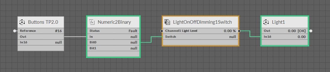
Add the LightOnOffDimming1Switch component to the application. Link the Bit slot from the Numeric2Binary component, corresponding to the source generic button, with the Switch slot of the LightOnOffDimming1Switch. Then, link the Channel1 Light Level slot of the LightOnOffDimming1Switch with the input slot of the AnalogDataPoint controlling the light.
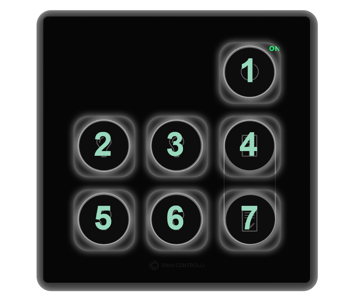
Generic buttons distribution
Various types of panels can be equipped with 2 to 7 of generic buttons:
-
Touch Point 4L1B 2.0: 7 generic buttons,
-
Touch Point ONE 2.0: 6 generic buttons (nos. 2, 3, 4, 5, 6, 7)
-
Touch Point 4L 2.0: 5 generic buttons (nos. 1, 2, 4, 5, 7),
-
Touch Point ONE 2L/1B 2.0: 2 generic buttons (nos. 4, 7).
Regardless of the above configurations, generic buttons are always numbered the same for programming:
Generic buttons LEDs
The generic buttons LEDs can be controlled with the GENERIC_BUTTON_LED_MODES and GENERIC_BUTTON_LED_BMS_STATES variables. Find out more: User Interface Parameters.