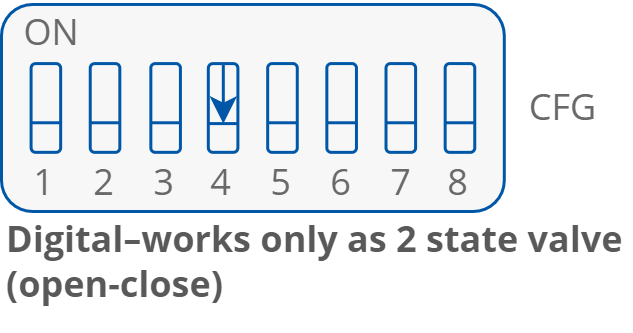
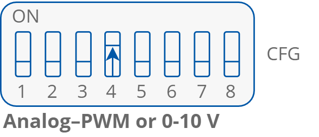
The figure belowThe controller’s outputs can operate in digital or analog mode. Depending on the fan coil unit actuators control type, the corresponding DIP switch has to be set to a desired position.
The figure below pictures the connection of heating actuators:
-
A1 for analog 0-10 V control;
-
TO1 for analog PWM or digital ON-OFF control;
-
O4 for digital ON-OFF control.
Note that, when using the second stage heating, the additional second stage heater can be controlled only by the O4 output, leaving the A1 or TO1 for the first stage. Otherwise, when using only the first stage heating, the O4 output can be used for digital control of the first stage heating actuator.
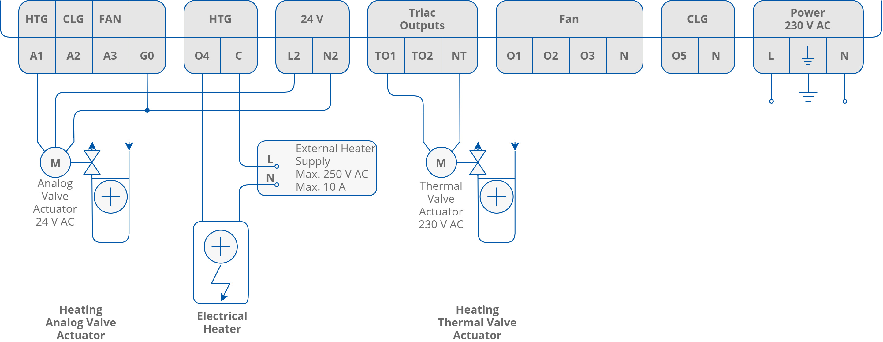
Heating actuators connection
The figure below pictures the connection of cooling actuators:
-
A1 for analog 0-10 V control while operating in 2-pipe mode;
-
A2 for analog 0-10 V control while operating in 4-pipe mode;
-
TO1 for analog PWM or digital ON-OFF control while operating in 2-pipe mode;
-
TO2 for analog PWM or digital ON-OFF control while operating in 4-pipe mode;
-
O5 for digital ON-OFF control.
Note that, when using the second stage cooling, the additional second stage cooler can be controlled only by the O5 output, leaving the A1, A2, TO1, or TO2 for the first stage. Otherwise, when using only the first stage cooling, the O5 output can be used for digital control of the first stage cooling actuator.
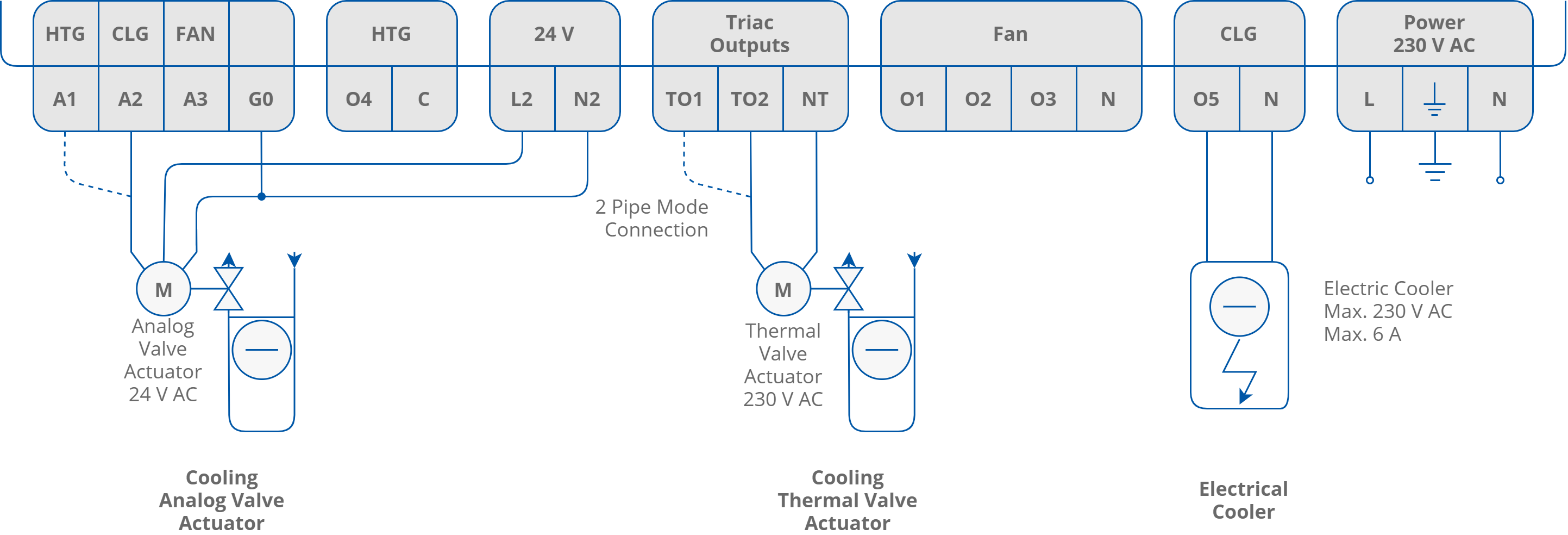
Cooling actuators connection
For more information on control types and connection details, check the iSMA-B-FCU Application manual and iSMA-B-FCU Hardware manual.