The default application has been designed to run with a wide range of typical fan coil units. Application adjustments are made with the S3 CFG DIP switch. The FCU application provides the following configurable modes:
-
pipe mode;
-
2-stage heating;
-
2-stage cooling;
-
heating/cooling control mode;
-
CV temperature source;
-
fan type.
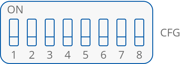
The CFG DIP switch
The status of DIP switch configuration is presented in the Dip_Switch_Configuration network variable.
The DIP switch function is presented in the table below:
|
No. |
Name |
On |
Off |
Default |
|
|---|---|---|---|---|---|
|
1 |
Pipe Mode |
2-Pipe |
4-Pipe |
4-Pipe |
|
|
2 |
Heating 2nd Stage |
Enable |
Disable |
Disable |
|
|
3 |
Cooling 2nd Stage |
Enable |
Disable |
Disable |
|
|
4 |
Heating/cooling control mode |
Analog |
Digital |
Digital |
|
|
No. |
Name |
Switches configuration |
Function |
Default |
|
|
5 |
CV temperature source |
5-Off |
6-Off |
LCD Panel |
LCD Panel |
|
5-Off |
6-On |
Room Sensor SI3 |
|||
|
6 |
5-On |
6-Off |
Air Return Temp SI1 |
||
|
5-On |
6-On |
Slave |
|||
|
7 |
Fan type |
7-Off |
8-Off |
Analog 0-10 V |
3-Speed |
|
7-Off |
8-On |
1-Speed |
|||
|
8 |
7-On |
8-Off |
2-Speed |
||
|
7-On |
8-On |
3-Speed |
|||
The CFG DIP switch configuration of particular switches