The iSMA-B-FCU device can work with a single heating device (1-stage only) or with two heating devices (basic, 1-stage, and additional, 2-stage). The type of operating stages is chosen by the S3 CFG DIP switch number 2.
1 Stage Heating
For the 1-stage only, depending on the control mode, the user can choose 1 of 3 outputs:
-
A1, analog output (only analog control mode);
-
TO1, triac output (digital and analog control modes);
-
O4, relay output (only digital control mode).
The connections of heating devices–in this example, the iSMA-B-FCU-HH version–is presented in the figure below.
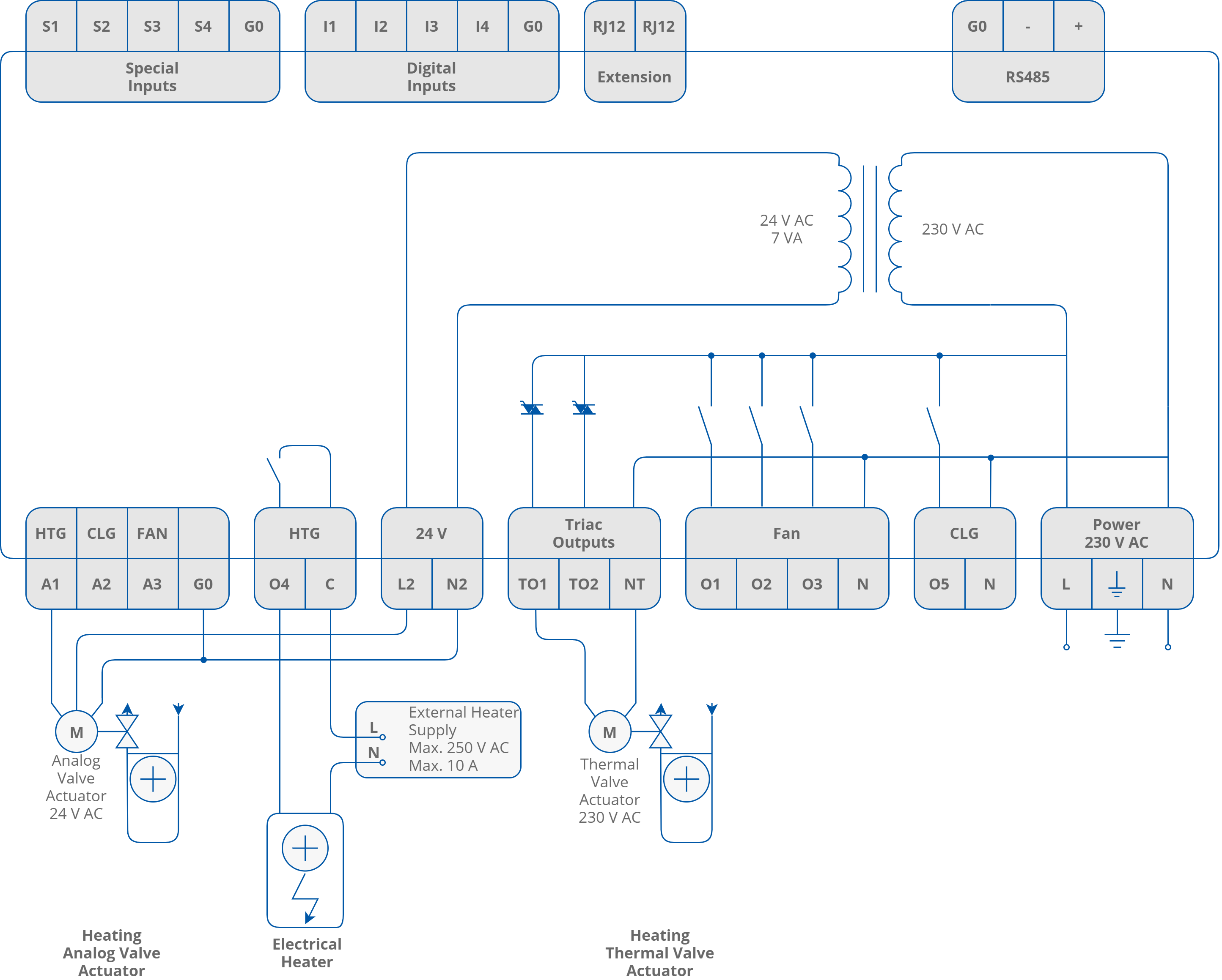
Example connection of FCU-HH heating devices
Digital Control Mode
In this mode, the control algorithm works as a typical thermostat, based on the Effective Setpoint and Control Value with heating the Diff parameter defined in the Heating_Binary_Diff network parameter. The output signal works in 2 states, low and high. In the 1st stage heating only, the user can choose 1 of 2 outputs: TO1, triac output, or O4, relay output. The A1 output is disabled. The high value of thermostat output also enables the operation of the fan. The algorithm of heating digital control mode is presented in the chart below.
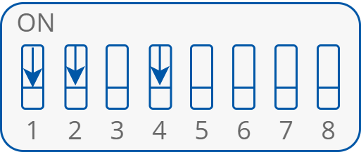
The CFG DIP switch configuration in digital control mode
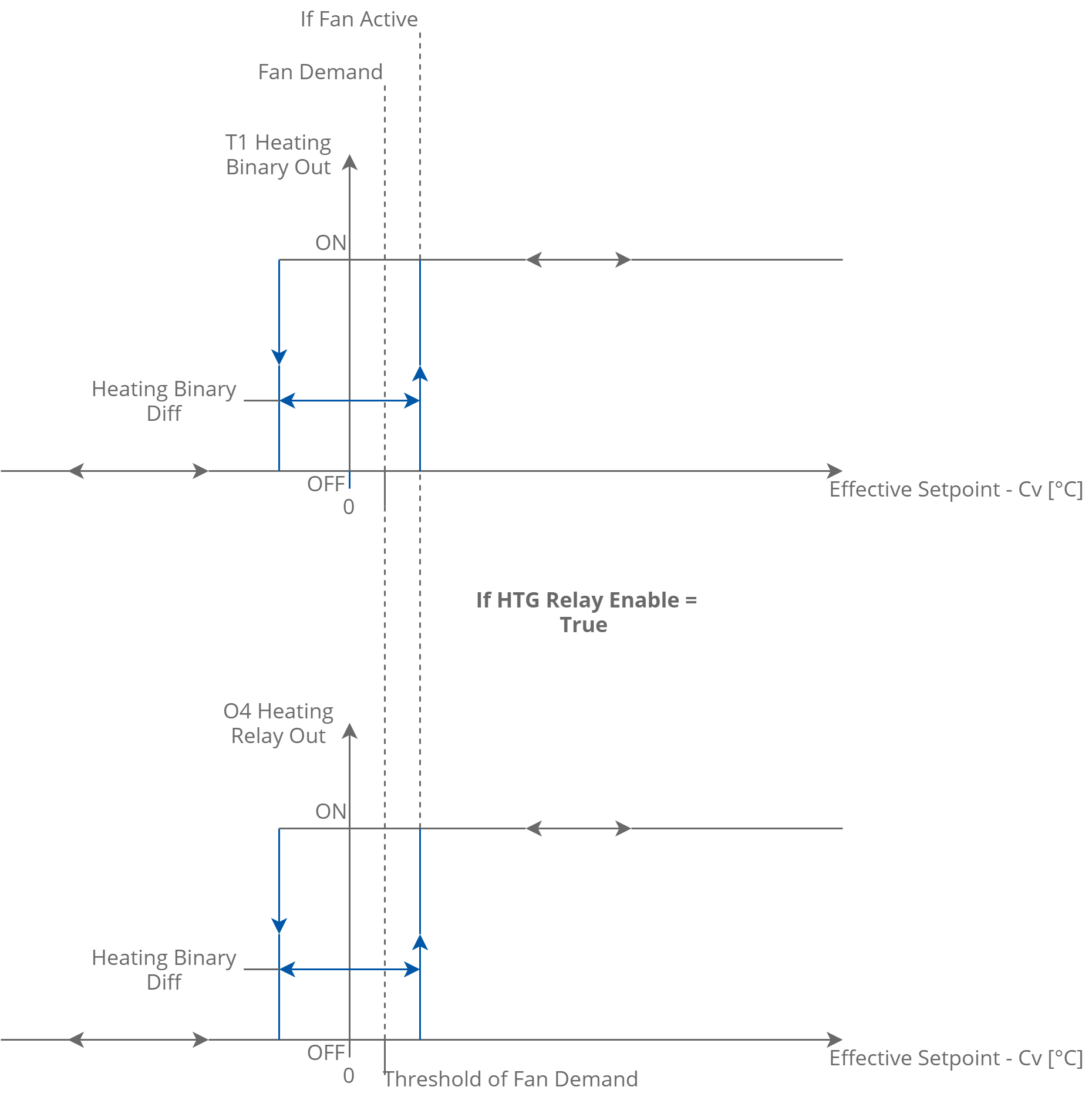
1 stage heating digital control mode
Note: The O4 HTG output relay can be enabled/disabled with the HTG_Relays_Enable network parameter, and by default this relay is enabled. If the output is not in use, it is recommended to disable it.
Analog Control Mode
In this mode, the algorithm is controlled by the PI regulator, which calculates the output value in the range from 0 to 100%, basing on the Effective_Setpoint and CV (room temperature) values. The PI regulator can be adjusted by Kp and Ti network parameters. In the 1st stage heating, the user can choose 1 of 2 outputs: A1, analog output, or TO1, triac output PWM. The O4 relay output is disabled. The A1 analog output value and the TO1 PWM signal is proportional to the PI regulator output. If the PI regulator output is equal or higher than 5%, it activates the fan (Fan Demand). The algorithm of heating analog control mode is presented in the chart below.
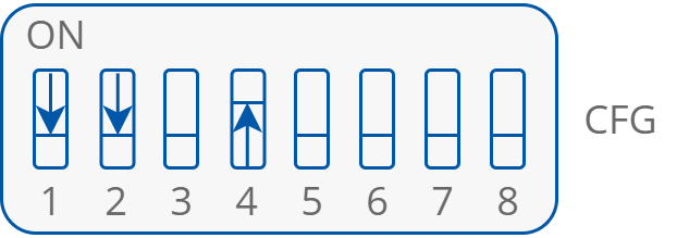
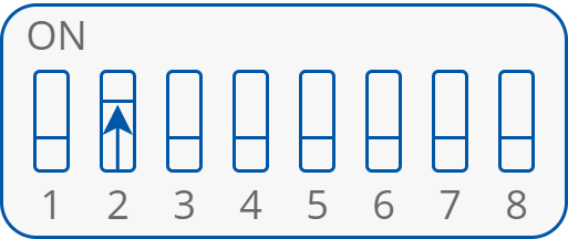
The CFG DIP switch configuration for analog control mode
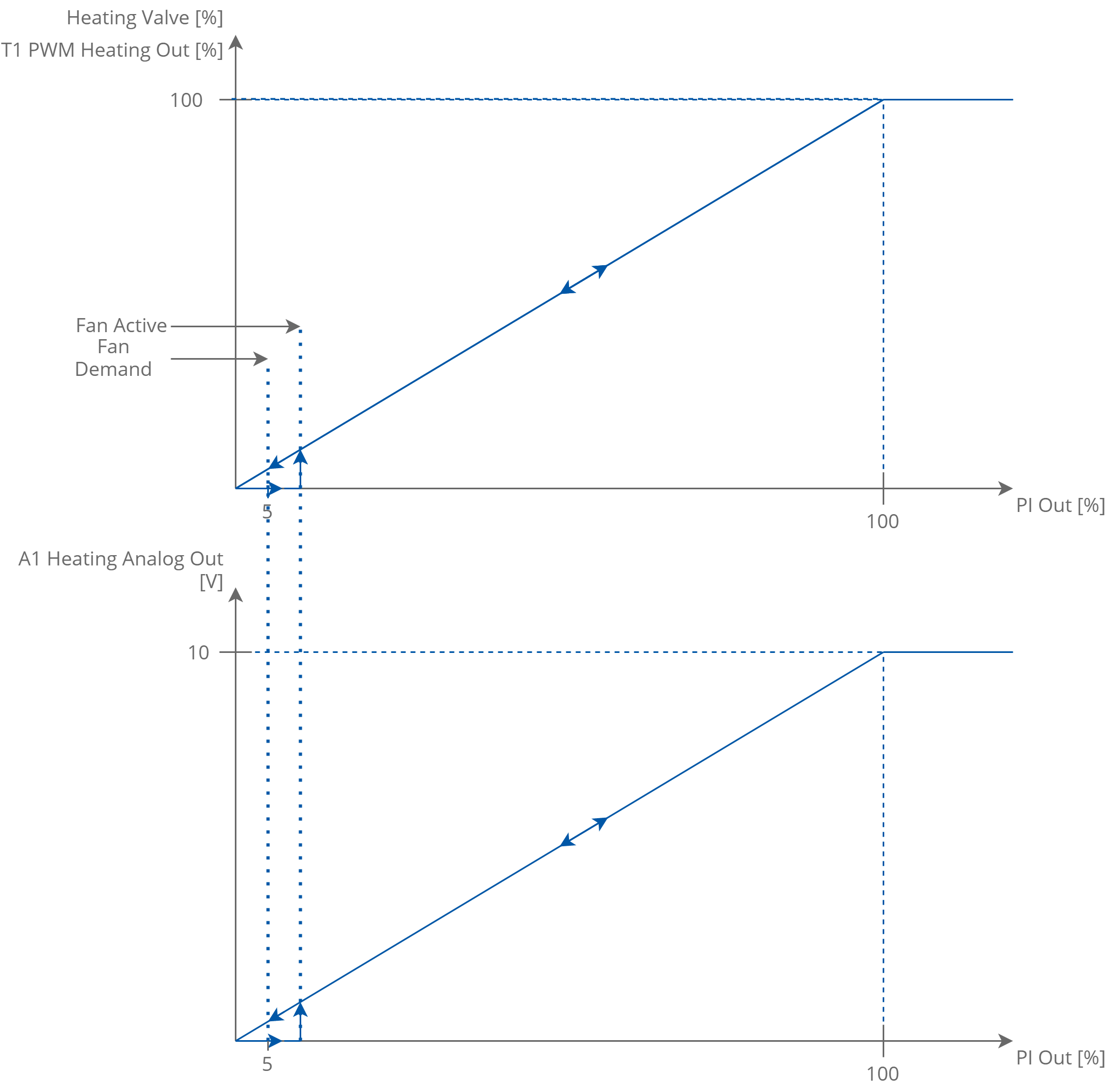
1 stage heating analog control mode
2 Stage Heating
As an additional 2nd stage heating, the default application can operate only with the O4 relay. The 2nd stage heating is activated by setting the CFG DIP (switch number 2 in on position).
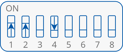
The CFG DIP switch configuration for 2 stage heating
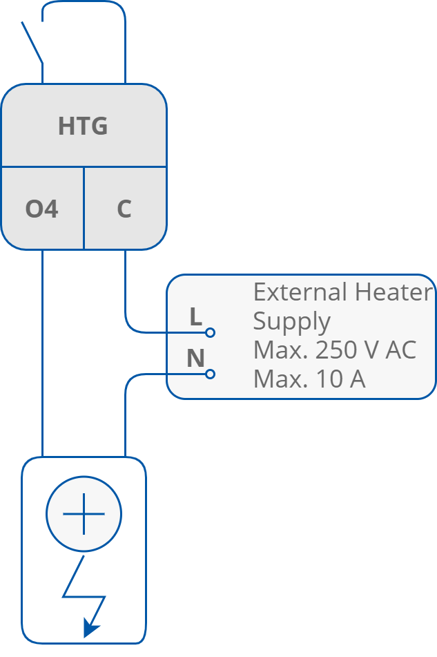
2nd stage electrical heater connection and heating 2nd stage of heating activated CFG DIP switch configuration
Digital Control Mode
In this mode, the control algorithm operates with 2 typical thermostats. 1st stage thermostat is based on the Effective Setpoint and Control Value with heating Diff parameters defined in the Heating_Binary_Diff network parameter. 2nd stage thermostat works with shifted Effective Setpoint and Control Value with heating Diff parameters defined in the Second_Stage_Diff_Binary network parameter. 2nd stage setpoint shifting value is defined in the Second_Stage_Threshold_Binary network parameter. 1st stage thermostat output high value also activates the fan. The output signals are working in 2 states, low and high. In the 1st stage heating, the user can use TO1 triac output only, and in the 2nd stage O4 relay output only. The A1 output is disabled. The heating digital control mode algorithm of the 2nd stage is presented in the chart below.
The CFG DIP switch configuration for digital control mode
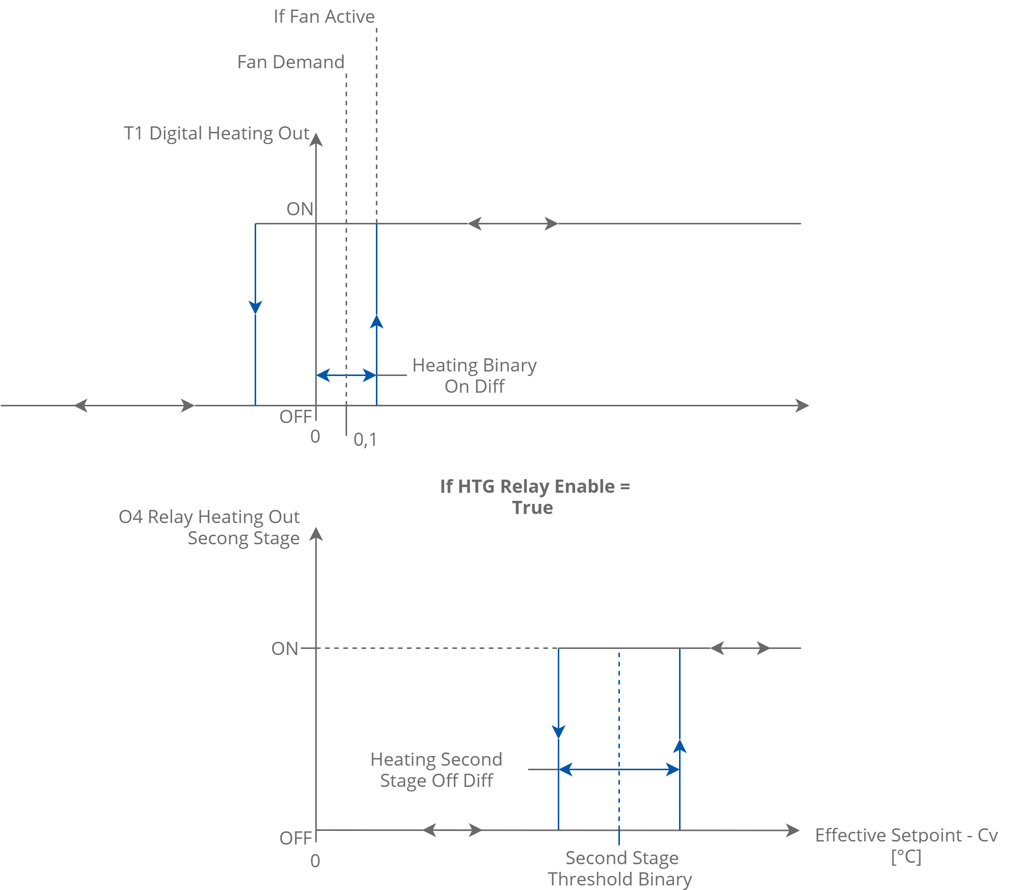
2 stage heating digital control mode
Analog Control Mode
In this mode, the algorithm is controlled by the PI regulator, which calculates the output value in the range from 0 to 100%, basing on the Effective_Setpiont and CV (room temperature) values. The PI regulator can be adjusted by Kp and Ti network parameters. The 1st stage analog signal is scaled from 0 to the Second_Stage_Threshold_Analog network parameter value. If the PI regulator output achieves the Second_Stage_Threshold_Analog value, the 1st stage analog signal achieves value of 100%. The 2nd stage works as a thermostat, basing on the Second_Stage_Threshold_Analog as setpoint, the PI regulator output as Control Value and Diff parameters defined in the Second_Stage_Diff_Analog network parameter. In the 1st stage of heating, the user can choose 1 of 2 outputs: A1, analog output or TO1, triac output PWM. The O4 relay output is dedicated to the 2nd stage. The A1 analog output value and TO1 PWM signal are proportional to the PI regulator output. If the PI regulator output is equal or higher than 5% of the fan, it activates the fan (Fan Demand). The analog control mode of the 2-stage heating is presented in the charts below.
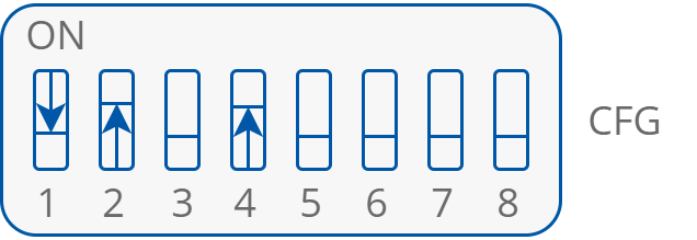
The CFG DIP switch configuration for analog control mode
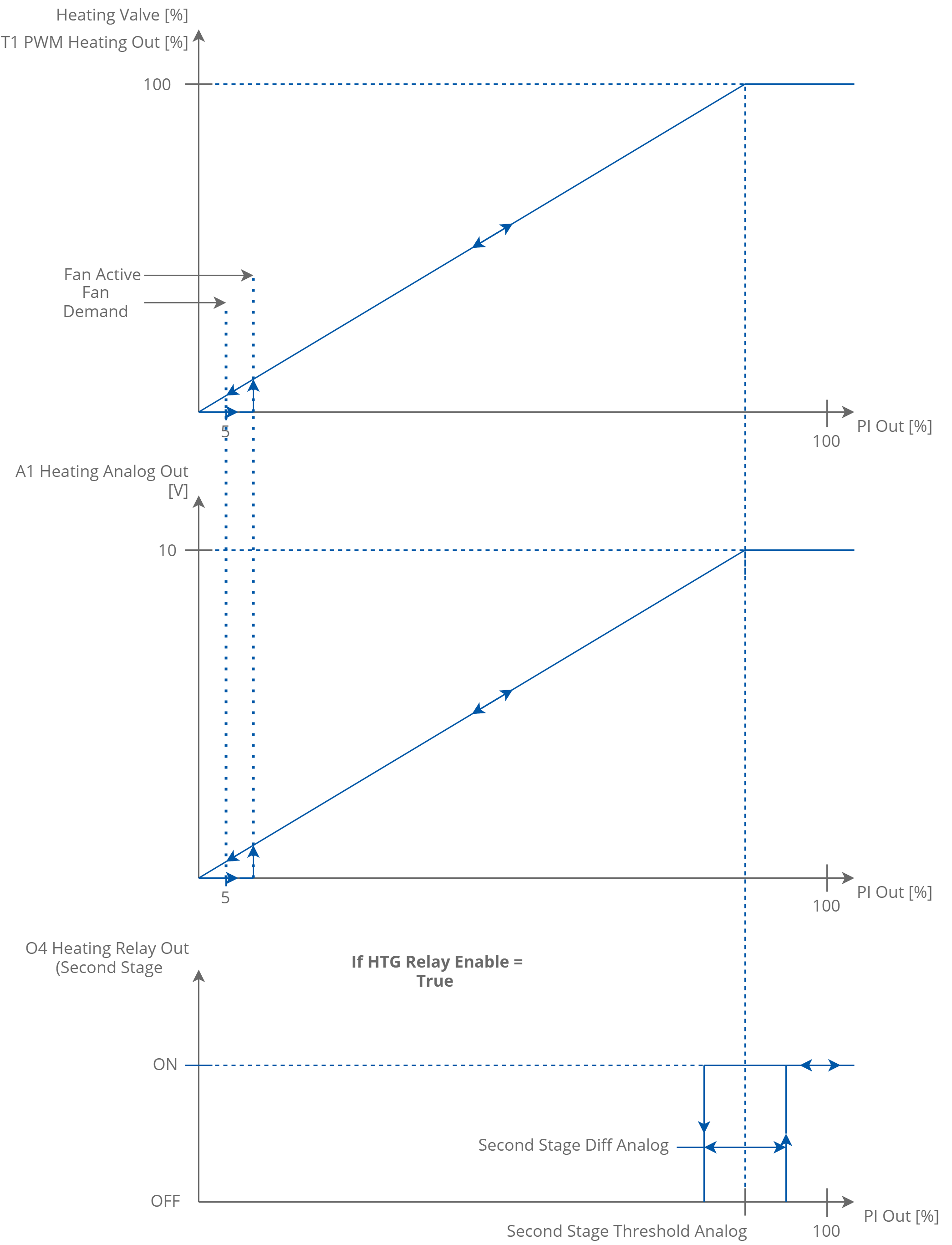
2-stage heating analog control mode