The UAC28-IP controller has a front panel equipped with LED status diodes and three configuration DIP switches.
LED Indicators

-
The ON LED (power) is on (green) when the controller is running properly. The ON LED blinks with 5 Hz frequency when the device is starting and during SD card diagnostics.
Note: If the frequent blinking continues for over 10-15 seconds, it means the SD card is being recovered as a result of the diagnostics process. Each time the device is started, it runs a diagnostic process, which checks if the SD card is available and the device is fully operable. If the diagnostics process does not return any necessary fixes, the blinking ceases after a few seconds.
-
The ALM LED (red) lights up if the device is in the emergency mode.
-
The ETH1 LED lights up (orange) after sending each data packet when connected to the programming tool. As long as the controller receives/sends packets, the LED blinks continuously.
-
The COM1 LED lights up for RS485 communication.
-
U1-U12 LEDs light up when resistance connected to the input is less than 5 kΩ (dry contact input is active).
-
I1-I4 LEDs light up when the connected contact is closed.
-
A1-A6 LEDs light up when the output’s voltage or PWM factor is different from 0, or the Out slot of the AnalogOutput component is true (when in digital mode).
-
O1-O6 LEDs light up when the Out slot of the DigitalOutput component is true.
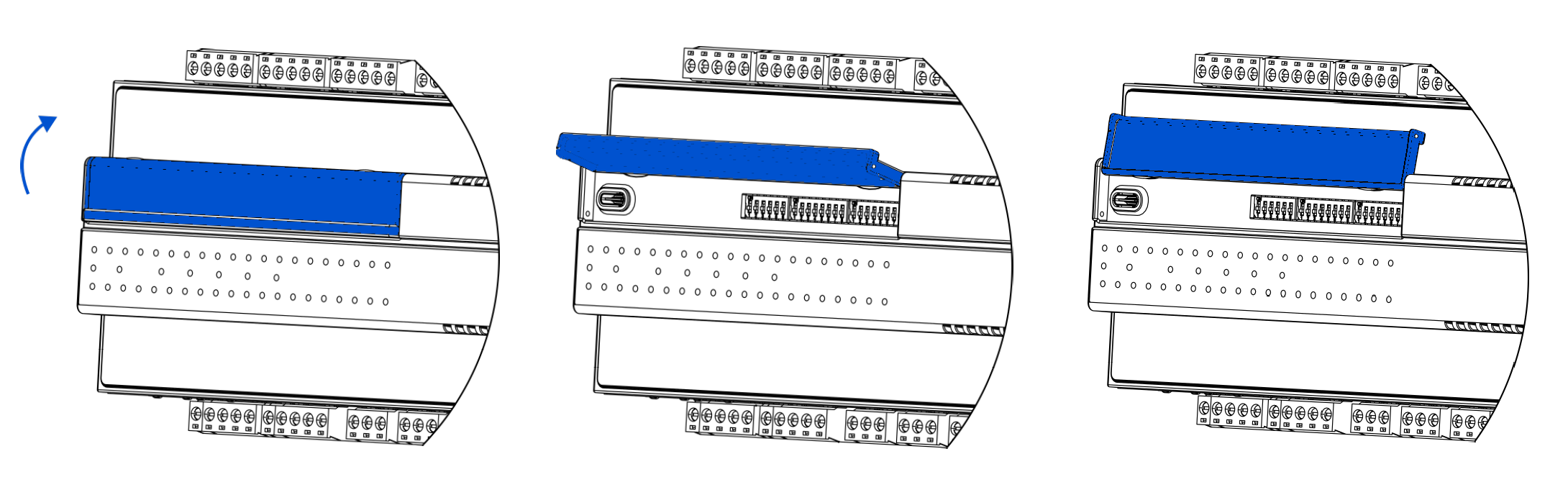
DIP Switches
The UAC28-IP device is equipped with three DIP switches, two 8-position ones (S2, S3) and a 6-position (S1). DIP switches can be freely used in client's application. Each of 6/8 switches has true or false state; they are dedicated for setting configuration in the user's application.
Note: The 6th switch on the S1 DIP switch is to restore factory default settings in the device.
To access DIP switches, lift the blue cover.