This section outlines all details regarding hardware specification of the Touch Point panel.
Panel Versions
Touch Point Series
Touch Point series - basic line of the Touch Point panels:
-
available with or without a display,
-
in different configurations of temperature, humidity, and CO2 sensors,
-
and 2 colors - black and white.
Touch Point VAV Series
Touch Point VAV series - line of the Touch Point panels with no fan control:
-
available with a display,
-
in different configurations of temperature, humidity, and CO2 sensors,
-
and 2 colors - black and white.
|
Model |
Panel Code |
Sensors |
Display |
Color |
||||
|---|---|---|---|---|---|---|---|---|
|
Temperature |
Humidity |
CO2 |
Yes |
No |
Black |
White |
||
|
Touch Point |
TP-B |
|
|
|
|
|
|
|
|
TP-W |
|
|
|
|
|
|
|
|
|
TP-H-B |
|
|
|
|
|
|
|
|
|
TP-H-W |
|
|
|
|
|
|
|
|
|
TP-C-B |
|
|
|
|
|
|
|
|
|
TP-C-W |
|
|
|
|
|
|
|
|
|
TP-HC-B |
|
|
|
|
|
|
|
|
|
TP-HC-W |
|
|
|
|
|
|
|
|
|
TP-DISP-B |
|
|
|
|
|
|
|
|
|
TP-DISP-W |
|
|
|
|
|
|
|
|
|
TP-H-DISP-B |
|
|
|
|
|
|
|
|
|
TP-H-DISP-W |
|
|
|
|
|
|
|
|
|
TP-C-DISP-B |
|
|
|
|
|
|
|
|
|
TP-C-DISP-W |
|
|
|
|
|
|
|
|
|
TP-HC-DISP-B |
|
|
|
|
|
|
|
|
|
TP-HC-DISP-W |
|
|
|
|
|
|
|
|
Touch Point panel models
|
Model |
Panel Code |
Sensors |
Display |
Color |
||||
|---|---|---|---|---|---|---|---|---|
|
Temperature |
Humidity |
CO2 |
Yes |
No |
Black |
White |
||
|
Touch Point VAV |
TP-VAV-DISP-B |
|
|
|
|
|
|
|
|
TP-VAV-DISP-W |
|
|
|
|
|
|
|
|
|
TP-VAV-H-DISP-B |
|
|
|
|
|
|
|
|
|
TP-VAV-H-DISP-W |
|
|
|
|
|
|
|
|
|
TP-VAV-C-DISP-B |
|
|
|
|
|
|
|
|
|
TP-VAV-C-DISP-W |
|
|
|
|
|
|
|
|
|
TP-VAV-HC-DISP-B |
|
|
|
|
|
|
|
|
|
TP-VAV-HC-DISP-W |
|
|
|
|
|
|
|
|
Touch Point VAV panel models
Legend:
-
H - a version with temperature and humidity sensors
-
C - a version with temperature and CO2 sensors
-
HC - a version with temperature, humidity, and CO2 sensors
-
B - black version
-
W - white version
Dimensions [mm]
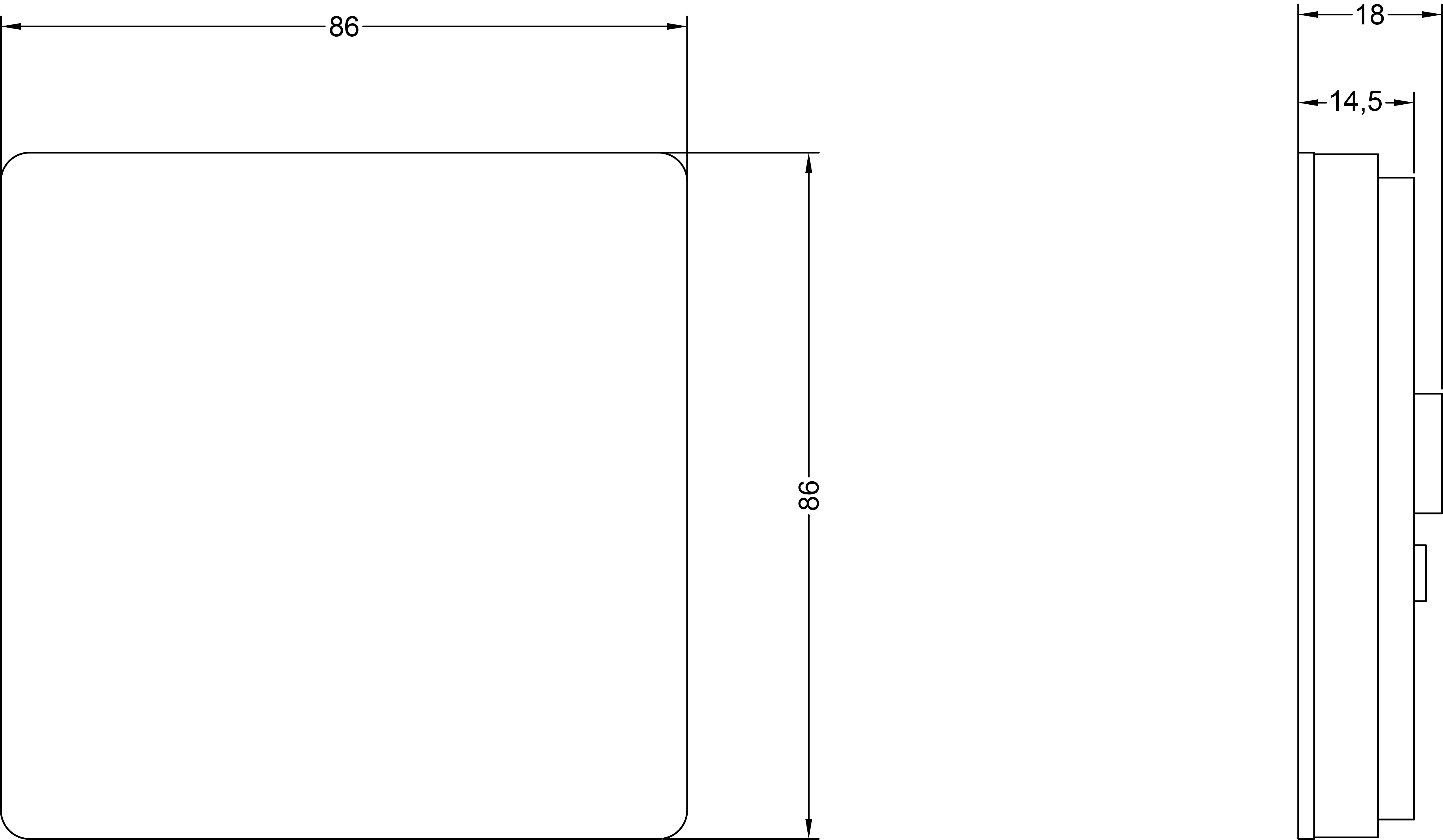
Touch Panel
|
|
-
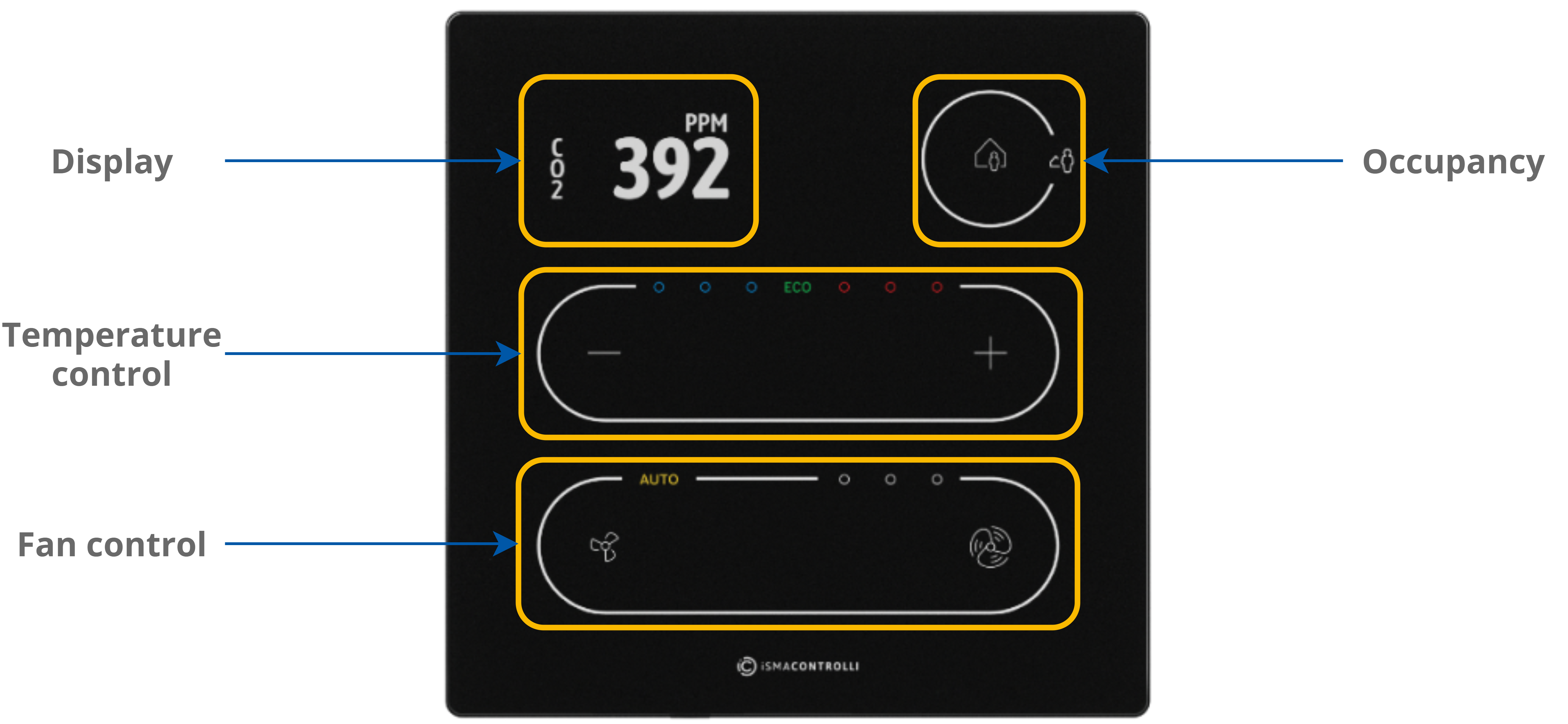
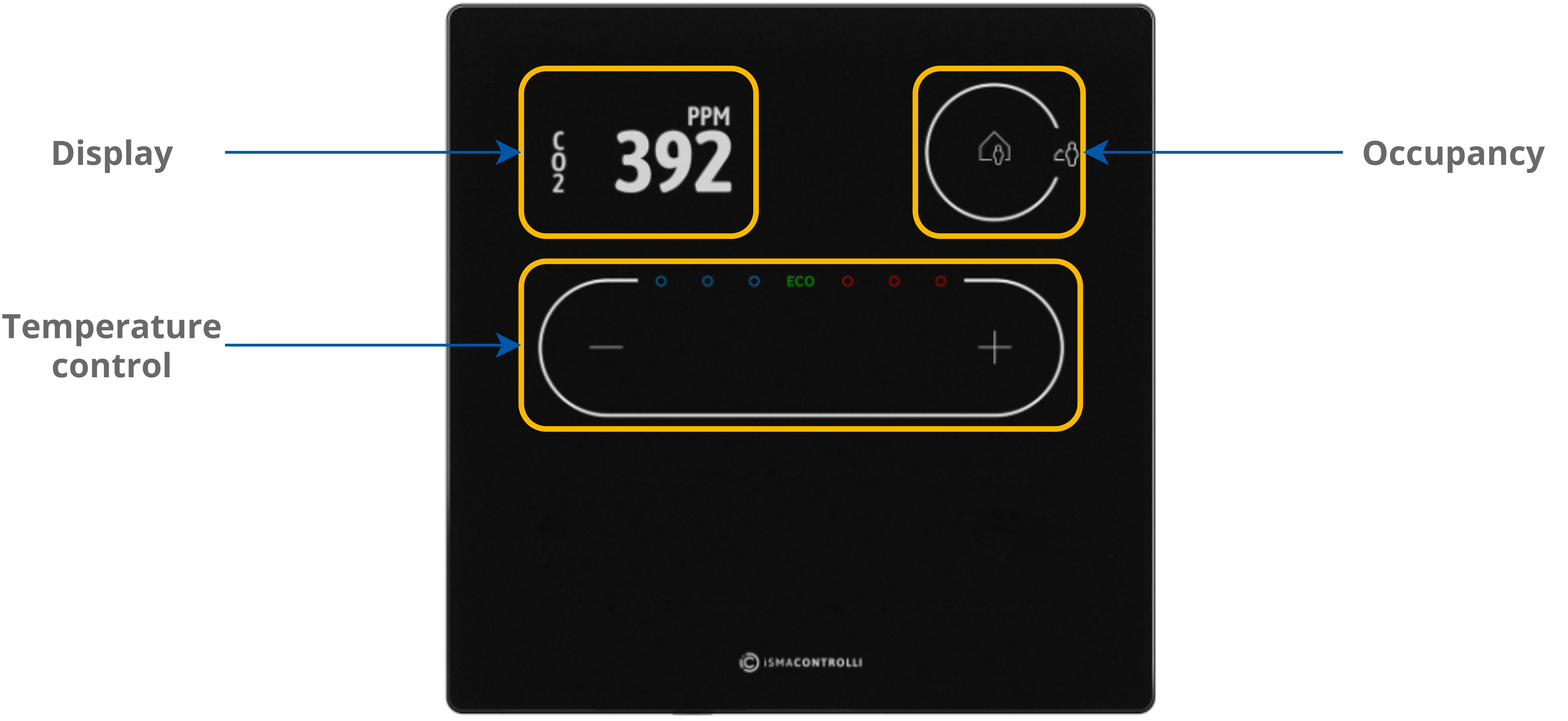
5 buttons for occupancy, temperature (–/+), and fan (small fan/big fan icons - only the Touch Point series) control;
-
3 blue and 3 red LEDs for temperature signalization;
-
3 white LEDs for fan signalization (only the Touch Point series);
-
1 white LED for fan auto mode signalization (only the Touch Point series).
Auto-calibration
Touch buttons are cyclically auto-calibrated. During the process, buttons are not responsive; in such case, wait a few seconds and press the button again.
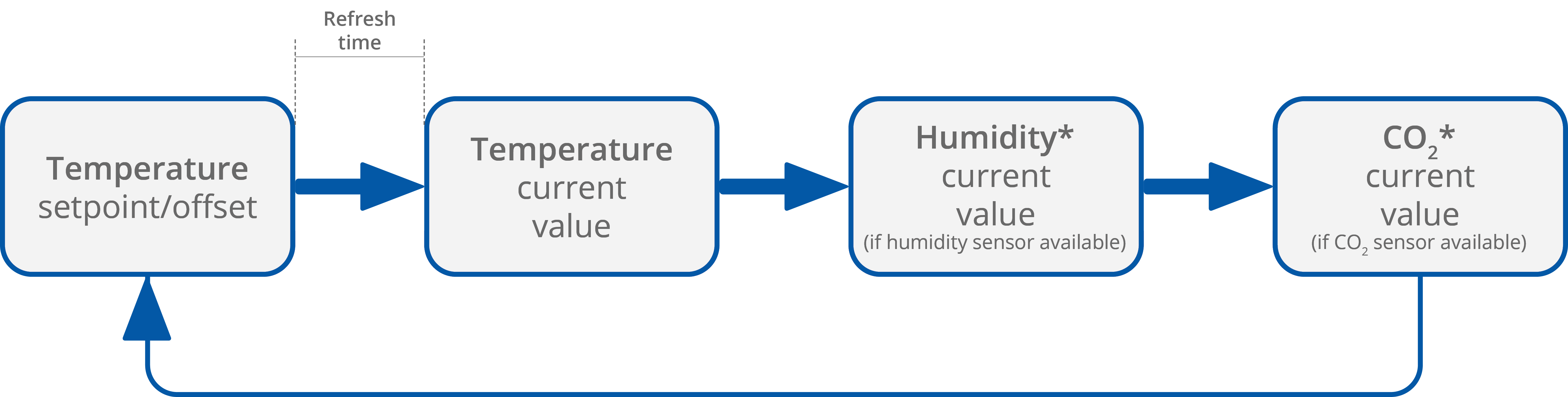
The LCD display shows following information:
-
temperature setpoint or offset (after pushing a + or – button, according to configuration);
-
temperature current value with unit;
-
humidity current value with unit (optionally);
-
CO2 current value with unit (optionally).
Note: Currently displayed parameters change with a frequency set in the 40217 register.
LEDs
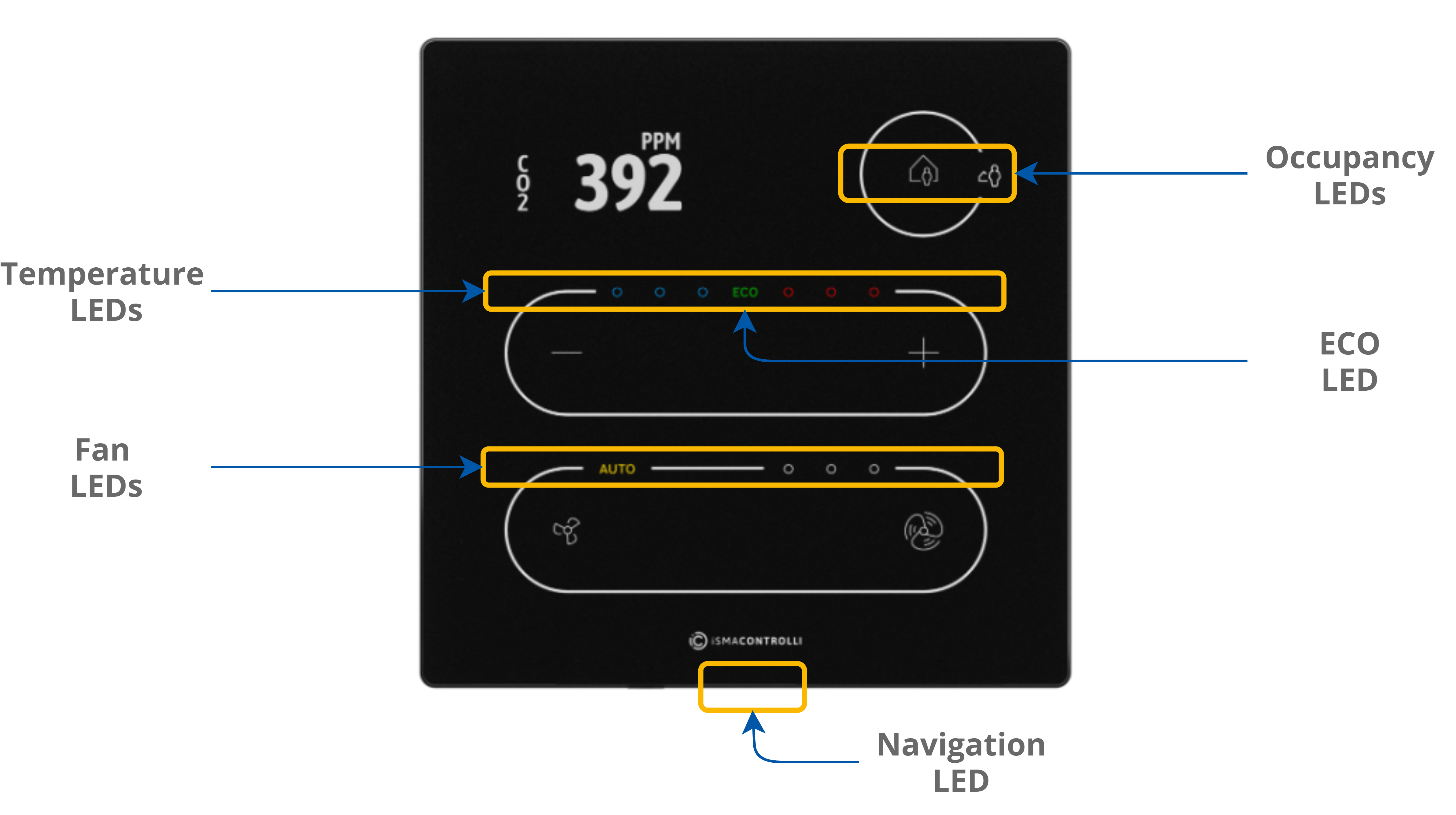
|
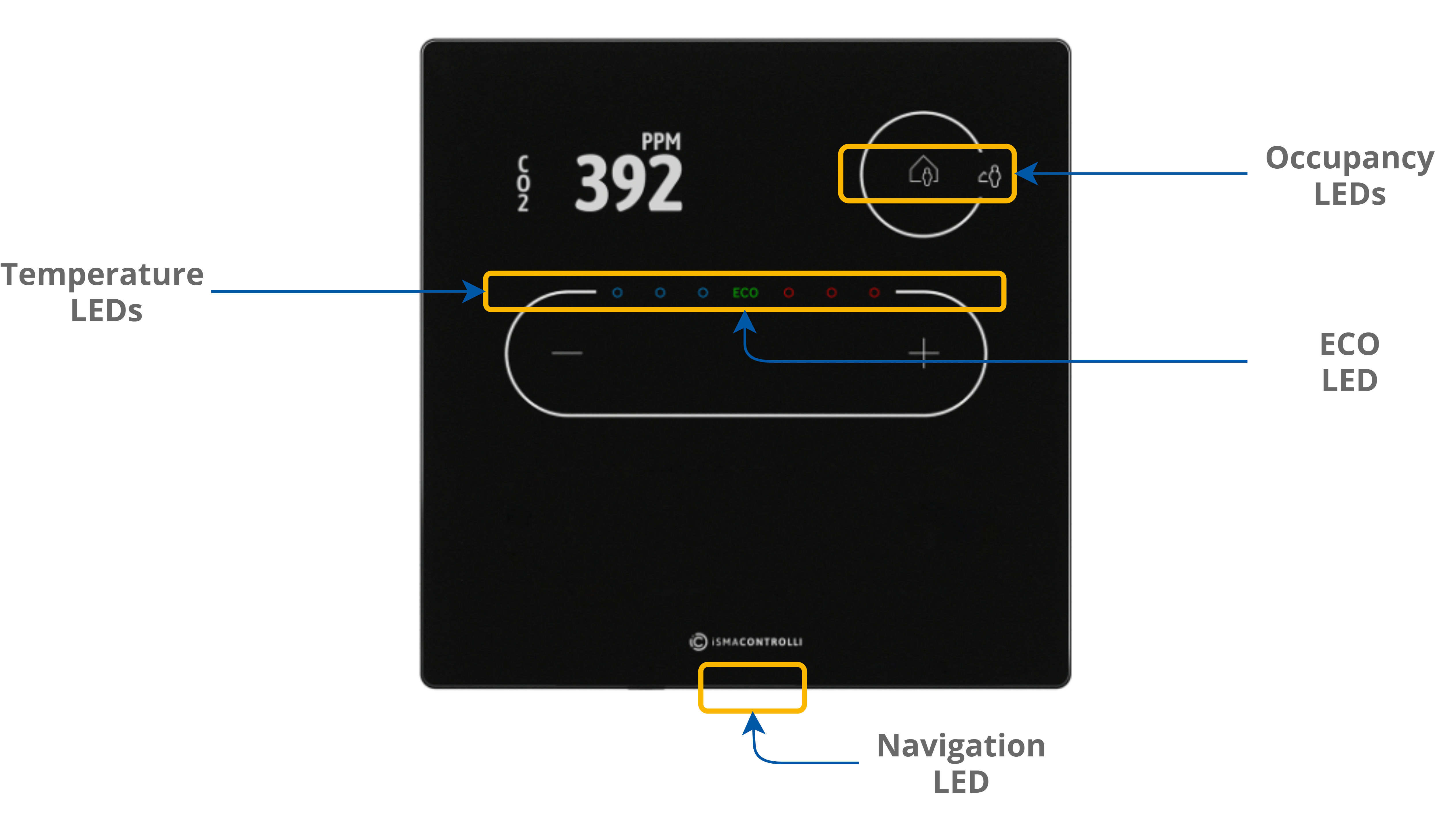
|
The panel is equipped with:
-
2 white LEDs for signalizing occupancy status;
-
3 blue and 3 red LEDs for temperature signalization (cooling or heating);
-
4 white LEDs for fan modes indication (only the Touch Point series);
-
1 ECO LED;
-
1 navigation LED to localize the panel in the dark.
LED Modes
The Touch Point panel works in 3 modes of LED lighting intensity:
-
active: the LED lighting mode after any button on the screen has been touched;
-
idle: the LED lighting mode after a time set from a last button has been touched;
-
standby: the LED lighting mode after a time set from going into the idle mode.
All lighting intensity values in these three different modes can be set in the 40207-40216 Modbus registers.
Buzzer
The Touch Point panel is equipped with a buzzer, which informs about a detected touch with a short sound.
The buzzer also provides a CO2 alarm function, which emits sounds once the CO2 level exceeds a set alarm value. The alarm can be confirmed and muted by pressing any button.
The buzzer may be activated or deactivated using the DEVICE_CONFIGURATION register/object (bit 0, BUZZER).
|
Register Value |
Description |
|---|---|
|
0 |
Buzzer deactivated |
|
1 |
Buzzer activated |
The BUZZER values
By default, the buzzer is active.