Special Application Modes for 4I4O-H, 4I4O-H-IP, 4U4O-H, and 4U4O-H-IP
The 4I4O-H, 4I4O-H-IP, 4U4O-H, 4U4O-H-IP modules have simple built-in applications, which can be used to control building devices. These applications control digital output states according to the signals from the digital input. The relation between inputs and outputs is shown in the table below, and it cannot be changed.
|
Digital Input |
Digital Output |
|---|---|
|
DI1 |
DO1 |
|
DI2 |
DO2 |
|
DI3 |
DO3 |
|
DI4 |
DO4 |
Built-in application determining the relation between input and output
The digital inputs in 4I4O-H, 4I4O-H-IP, 4U4O-H, 4U4O-H-IP modules can be set to work in different modes. There are dedicated objects for input mode (Multistate Value 27-30), time parameters (Analog Value 26-29), setpoints for heating/cooling modes (Analog Value 30-33–4U4O-H and 4U4O-H-IP only), and for differential value in heating/cooling modes (Analog Value 34-37–4U4O-H and 4U4O-H-IP only).
INPUT MODE Object (Multistate Value: 27-30)
This object contains information about the operating mode of the module. Available modes and multistate object values are shown in the table below:
|
Value |
OPERATING MODE |
|---|---|
|
1 |
Ordinary IO(def) |
|
2 |
Monostable Relay |
|
3 |
Bistable Relay |
|
4 |
Time Relay NO [ms] |
|
5 |
Time Relay NC [ms] |
|
6 |
Time Relay NO [s] |
|
7 |
Time Relay NC [s] |
|
8 |
Input Forwarding |
|
9 |
Heating (4U4O-H and 4U4O-H-IP only) |
|
10 |
Cooling (4U4O-H and 4U4O-H-IP only) |
The Input Mode object value list
The operating mode can be changed by entering the right value into the Input Mode object.
Special modes are initialized after 3 seconds from the power-up or restart of the module (the time value needed to stabilize the operation of the analog transmitter). Each input mode change sets corresponding output to the default state and resets the timer (used in the time-based modes).
Ordinary IO
Inputs and outputs operate as standard IO; inputs and outputs are not related to each other.
Monostable Relay
In this mode, the digital output reflects the corresponding state of the digital Input. The action of the monostable relay can be executed remotely by changing the relevant COMMAND object. The outputs can be also overwritten by the DIGITAL OUTPUT object, which allows for allows remote control from the BMS.
Bistable Relay
In this mode, only the rising edge on the digital input changes the output state. The action of the bistable relay can be executed remotely by changing the relevant COMMAND object. Outputs can be also overwritten by the DIGITAL OUTPUT object, which allows remote control from the BMS.
Time Relay NO [ms]
In this mode, if the output value is false, the rising edge on the digital input sets the output to true. Every falling edge on the digital input restarts the counter, which means that the output stays true for the time defined in the MODE TIME object (expressed in milliseconds), counting from the last falling edge of the digital input. The action of the time relay can be executed remotely by changing state from false to true in the relevant COMMAND object. The outputs can be also overwritten by the DIGITAL OUTPUT object, which allows remote control from the BMS.
Time Relay NC [ms]
In this mode, if the output value is false, the falling edge on the digital input sets the output to a true value. Every rising edge on the digital input starts the counter from the beginning, which means that the output stays true for the time defined in the MODE TIME object (expressed in milliseconds), counting from the last rising edge of the digital input. The action of time relay can be executed remotely by changing state from false to true in the relevant COMMAND object. The outputs can be also overwritten by the DIGITAL OUTPUT object, which allows remote control from the BMS.
Time Relay NO [s]
In this mode, if the output value is false, the rising edge on the digital input sets the output to true. Every falling edge on the digital input restarts the counter, which means that the output stays true for the time defined in the MODE TIME object (expressed in seconds), counting from the last falling edge of the digital input. The action of the time relay can be executed remotely by changing state from false to true in the relevant COMMAND object. The outputs can be also overwritten by the DIGITAL OUTPUT object, which allows remote control from the BMS.
Time Relay NC [s]
In this mode, if the output value is false, the falling edge on the digital input sets the output to true. Every rising edge on the digital input restarts the counter, which means that the output stays true for the time defined in the MODE TIME object (expressed in seconds), counting from the last rising edge of the digital input. The action of time relay can be executed remotely by changing state from false to true in relevant COMMAND object. The outputs can be also overwritten by the DIGITAL OUTPUT object module, which allows remote control from the BMS.
Input Forwarding
In this mode, any signal from the input is transferred directly to the assigned output without any modifications. Operation in the input forwarding mode can be stopped by the Block Input function.
Heating Mode (4U4O-H and 4U4O-H-IP Only)
In this mode, the output is controlled like a typical thermostat, basing on the Setpoint object and the Control value (Input value) with differential parameter defined in the Differential object. The output signal works in 2 states: low and high.
If the Control value is less than or equals to the difference between the Setpoint object and Differential object, the output is in the low state.
If the Control value is greater than or equals to the sum of the Setpoint object and Differential object, the output is in the high state.
The output in the low state:
Control value >= Setpoint + Differential
The output in the high state:
Control value <= Setpoint – Differential
The heating mode algorithm is shown in the chart below:
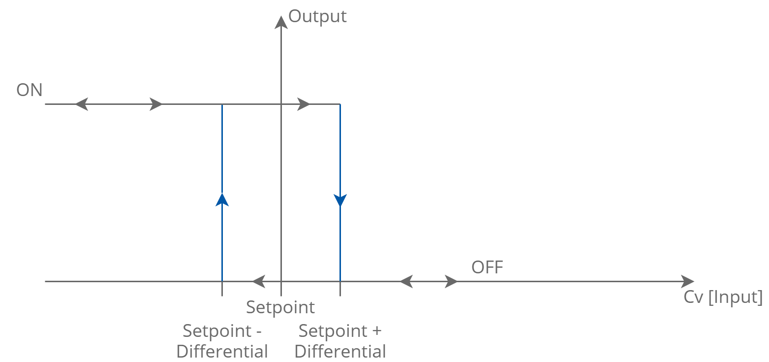
The heating mode algorithm
WARNING!
In case if the temperature sensor fails (if it is disconnected or shorted), the heating mode does not work, and the output remains in the false state.
Cooling Mode (4U4O-H and 4U4O-H-IP Only)
In this mode, the output is controlled like a typical thermostat, based on the Setpoint object and Control value (Input signal) with a differential parameter defined in the Differential object.
The output signal works in 2 states - low and high.
If the Control value is less than or equals to the difference between the Setpoint object and Differential object, the output is in the low state.
If the Control value is greater than or equals to the sum of the Setpoint object and Differential object, the output is in the high state.
The output in the low state:
Control value <= Setpoint – Differential
The output in the high state:
Control value >= Setpoint + Differential
The cooling mode algorithm is shown in the chart below:
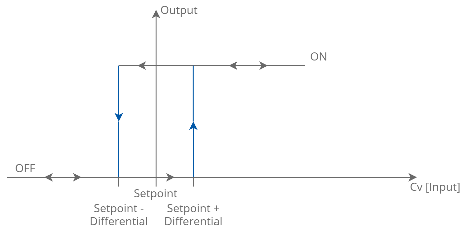
The cooling mode algorithm
WARNING!
In case if the temperature sensor fails (if it is disconnected or shorted), the heating mode does not work, and the output remains in the false state.
MODE TIME Object (Analog Value: 26-29)
This object contains the time value for TIME RELAY modes. The time unit depends on the selected mode: milliseconds or seconds.
COMMAND Object (Binary Value: 12-15)
The module includes special COMMAND objects. The command objects are used to remotely execute the action (simulate light switch/PIR). The action is executed by changing the state of the object from false to true. All special application modes can be executed except for input forwarding, heating and cooling modes.
BLOCKING Object (Binary Value: 8-11)
The BLOCKING objects are used to block physical input signals from the control logic (all modes excluding heating/cooling mode). By setting true value on the relevant object, the module blocks the input, and no action will be executed. Setting false value restores normal operation. The block input function does not work if the heating/cooling input mode is set.
SETPOINT Object (Analog Value: 30-33)
The SETPOINT objects contain values which are used in heating/cooling modes (4U4O-H and 4U4O-H-IP only) as the setpoints for heating/cooling control algorithm.
The default Setpoint value is 21.
DIFFERENTIAL Object (Analog Value: 34-37)
The DIFFERENTIAL objects contain values, which are used in heating/cooling modes (4U4O-H and 4U4O-H-IP only) as the differential for heating/cooling control algorithm. The Setpoint objects and Differential objects create a deadband of the Control values, which has no influence on the output.
Deadband = (Setpoint – Differential, Setpoint + Differential)
The default Differential value is 1.