The ZAC24-IP-D is a DALI-2 controller which can be conveniently integrated with Touch Point 2.0 panels for smooth and efficient light, blind, and HVAC control.
The Touch Point 2.0 panels have been specifically designed to facilitate a fully-functioning light control based on the cooperation with the ZAC24-IP-D DALI-2 controller and nano EDGE ENGINE libraries from OS V1.10.
The Touch Point 2.0 panels include the following series suitable for light control:
Touch Point ONE 2.0
Touch Point ONE 2.0 series - line of all-in-one room control Touch Point 2.0 panels:
-
equipped with a display,
-
with occupancy control button,
-
TP ONE 2.0: with 6 generic buttons,
-
TP ONE 2L/1B 2.0: with setpoint and fan control dedicated buttons and 2 generic buttons,
-
with LED indicators,
-
available in different configurations of sensors (temperature, CO2, and humidity),
-
available in different configurations of colors (black or white).
Touch Point Light&Blind 2.0
Touch Point Light & Blind 2.0 series - line of the Touch Point 2.0 panels with light and blind control buttons:
-
glass front without a display,
-
with master power button programmable for light and blind control,
-
with generic buttons,
-
with LED indicators,
-
available in different configurations of colors (black or white).
The following section describes integration steps to connect the ZAC24-IP_D controller with a compatible Touch Point 2.0 panel.
Touch Point ONE 2.0
The Touch Point ONE 2.0 panel is programmed with the use of the TpOneControlLogic component from the nano EDGE ENGINE’s ComfortControl library. The component offers a pre-configured logic for the generic buttons functional distribution on the Touch Point ONE 2.0 touch panel.
Step 1: Connection
Make sure that the Touch Point ONE 2.0 panel and the controller are powered and correctly connected to the network.
In the nano EDGE ENGINE software tool (iC Tool/nE2 Link module), go to the Networks container, Modbus network (Modbus is recommended).
Recommended parameters
It is recommended to set the polling mode to fast with the fast mode parameter set to 100 ms.
Add devices to the network and address them properly.
Step 2: Points
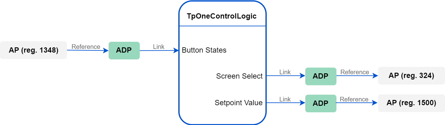
For a correct connection with the TpOneControlLogic component, it is required to add the following three network points to the Modbus device:
-
AnalogPoint for the generic buttons state register (Address slot: 1348),
-
AnalogPoint for the screen select mode register (Address slot: 324),
-
AnalogPoint for the temperature setpoint register (Address slot: 1500).
Step 3: TpOneControlLogic component
Add the TpOneControlLogic component (from the ComfortControl library) to the application.
Recommended parameters
It is recommended to add the TpOneControlLogic component to the application, which scan time is set to 100 ms. Slower applications may hinder a proper operation of the component.
Step 4: Data Points and Linking
Add three AnalogDataPoints to the same application, where the TpOneControlLogic component has been added.
Create the following Reference Link from the Reference slot in the network point to the Reference slot in the Data Point:
-
AnalogPoint for the generic buttons state to the first AnalogDataPoint.
Create the following Reference Links from the Reference slot in the Data Point to the Reference slot in the network point:
-
AnalogDataPoint to the AnalogPoint for the screen select mode,
-
AnalogDataPoint to the AnalogPoint for the temperature setpoint.
Create the following links with the TpOneControlLogic component:
-
(incoming) AnalogDataPoint’s (referenced to generic buttons register) Out slot to the Button States slot,
-
(outgoing) the Screen Select slot to the In slot of the AnalogDataPoint referenced to the screen select mode register,
-
(outgoing) the Setpoint Value slot to the In slot of the AnalogDataPoint referenced to the temperature setpoint register.
If required, configure the rest of the TpOneControlLogic component slots as necessary.
Touch Point ONE 2L/1B 2.0 and Touch Point Light&Blind 2.0
The Touch Point ONE 2L/1B 2.0 and Touch Point Light&Blind 2.0 panels are equipped with generic buttons, which can be programmed with the use of the GENERIC_BUTTON_STATES register.
Step 1: Connection
Make sure that the Touch Point ONE 2L/1B 2.0/Touch Point Light&Blind 2.0 panel and controller are powered and correctly connected to the network.
In the nano EDGE ENGINE software tool (iC Tool/nE2 Link module), go to the Networks container, Modbus network (Modbus is recommended).
Recommended parameters
It is recommended to set the polling mode to fast with the fast mode parameter set to 100 ms.
Add devices to the network and address them properly.
Step 2: Point
Add the following the network point to the Modbus device:
-
AnalogPoint for the generic buttons state register (Address slot: 1348).
Step 3: Data Point and Linking
Add the AnalogDataPoint to the application.
Recommended parameters
It is recommended to add the Data Point to the application, which scan time is set to 100 ms. Slower applications may hinder a proper data transmission between the panel and the controller.
Create the Reference Link from the AnalogPoint for the generic buttons state to the AnalogDataPoint (from the Reference slot in the network point to the Reference slot in the Data Point).
Step 4: Bits
Add the Numeric2Binary component to the same application, where the AnalogDataPoint has been added.
Link the AnalogDataPoint’s Out slot to the In slot of the Numeric2Binary component. Use the Numeric2Binary bits slots to link the data from the corresponding generic button in the application (for example, to the components from the LightControl library).
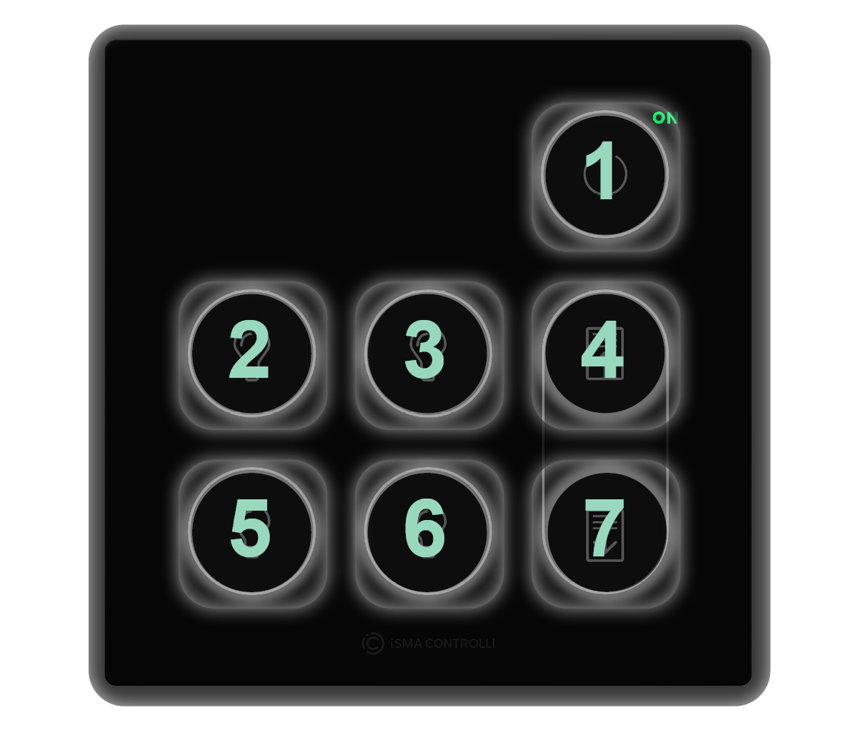
The GENERIC_BUTTON_STATES register contains information about generic buttons states on bits 0-6:
|
Button no. |
Bit |
|---|---|
|
1 |
0 |
|
2 |
1 |
|
3 |
2 |
|
4 |
3 |
|
5 |
4 |
|
6 |
5 |
|
7 |
6 |
Generic buttons distribution
Various types of panels can be equipped with 2 to 7 of generic buttons:
-
Touch Point 4L1B 2.0: 7 generic buttons,
-
Touch Point ONE 2.0: 6 generic buttons (nos. 2, 3, 4, 5, 6, 7)
-
Touch Point 4L 2.0: 5 generic buttons (nos. 1, 2, 4, 5, 7),
-
Touch Point ONE 2L/1B 2.0: 2 generic buttons (nos. 4, 7).
Regardless of the above configurations, generic buttons are always numbered the same for programming: