This section outlines all details regarding hardware specification of the Touch Point panel.
Panel Versions
Touch Point Series
|
|
Touch Point series - basic line of the Touch Point panels:
-
with or without a display,
-
with occupancy, setpoint control, and fan control buttons,
-
with LED indicators,
-
available in different configurations of sensors (temperature, CO2, and humidity),
-
available in different configurations of colors (black or white).
|
Model |
Panel Code |
Sensors |
Display |
Color |
||||
|---|---|---|---|---|---|---|---|---|
|
Temperature |
Humidity |
CO2 |
Yes |
No |
Black |
White |
||
|
Touch Point |
TP-B |
|
|
|
|
|
|
|
|
TP-W |
|
|
|
|
|
|
|
|
|
TP-H-B |
|
|
|
|
|
|
|
|
|
TP-H-W |
|
|
|
|
|
|
|
|
|
TP-C-B |
|
|
|
|
|
|
|
|
|
TP-C-W |
|
|
|
|
|
|
|
|
|
TP-HC-B |
|
|
|
|
|
|
|
|
|
TP-HC-W |
|
|
|
|
|
|
|
|
|
TP-DISP-B |
|
|
|
|
|
|
|
|
|
TP-DISP-W |
|
|
|
|
|
|
|
|
|
TP-H-DISP-B |
|
|
|
|
|
|
|
|
|
TP-H-DISP-W |
|
|
|
|
|
|
|
|
|
TP-C-DISP-B |
|
|
|
|
|
|
|
|
|
TP-C-DISP-W |
|
|
|
|
|
|
|
|
|
TP-HC-DISP-B |
|
|
|
|
|
|
|
|
|
TP-HC-DISP-W |
|
|
|
|
|
|
|
|
Touch Point panel models
Touch Point VAV Series
Touch Point VAV series - line of the Touch Point panels with no fan control buttons:
-
with a display,
-
with occupancy and setpoint control buttons,
-
with LED indicators,
-
available in different configurations of sensors (temperature, CO2, and humidity),
-
available in different configurations of colors (black or white).
|
Model |
Panel Code |
Sensors |
Display |
Color |
||||
|---|---|---|---|---|---|---|---|---|
|
Temperature |
Humidity |
CO2 |
Yes |
No |
Black |
White |
||
|
Touch Point VAV |
TP-VAV-DISP-B |
|
|
|
|
|
|
|
|
TP-VAV-DISP-W |
|
|
|
|
|
|
|
|
|
TP-VAV-H-DISP-B |
|
|
|
|
|
|
|
|
|
TP-VAV-H-DISP-W |
|
|
|
|
|
|
|
|
|
TP-VAV-C-DISP-B |
|
|
|
|
|
|
|
|
|
TP-VAV-C-DISP-W |
|
|
|
|
|
|
|
|
|
TP-VAV-HC-DISP-B |
|
|
|
|
|
|
|
|
|
TP-VAV-HC-DISP-W |
|
|
|
|
|
|
|
|
Touch Point VAV panel models
Touch Point Network Sensor Series
Touch Point Network Sensor series - line of the Touch Point multisensor panels:
-
glass front without a display and buttons,
-
one navigation LED,
-
available in different configurations of sensors (temperature, CO2, and humidity),
-
available in different configurations of colors (black or white).
|
Model |
Panel Code |
Sensors |
Color |
|||
|---|---|---|---|---|---|---|
|
Temperature |
Humidity |
CO2 |
Black |
White |
||
|
Touch Point Network Sensor |
TP-NS-B |
|
|
|
|
|
|
TP-NS-W |
|
|
|
|
|
|
|
TP-NS-H-B |
|
|
|
|
|
|
|
TP-NS-H-W |
|
|
|
|
|
|
|
TP-NS-C-B |
|
|
|
|
|
|
|
TP-NS-C-W |
|
|
|
|
|
|
|
TP-NS-HC-B |
|
|
|
|
|
|
|
TP-NS-HC-W |
|
|
|
|
|
|
Touch Point VAV panel models
Legend:
-
H - a version with temperature and humidity sensors
-
C - a version with temperature and CO2 sensors
-
HC - a version with temperature, humidity, and CO2 sensors
-
B - black version
-
W - white version
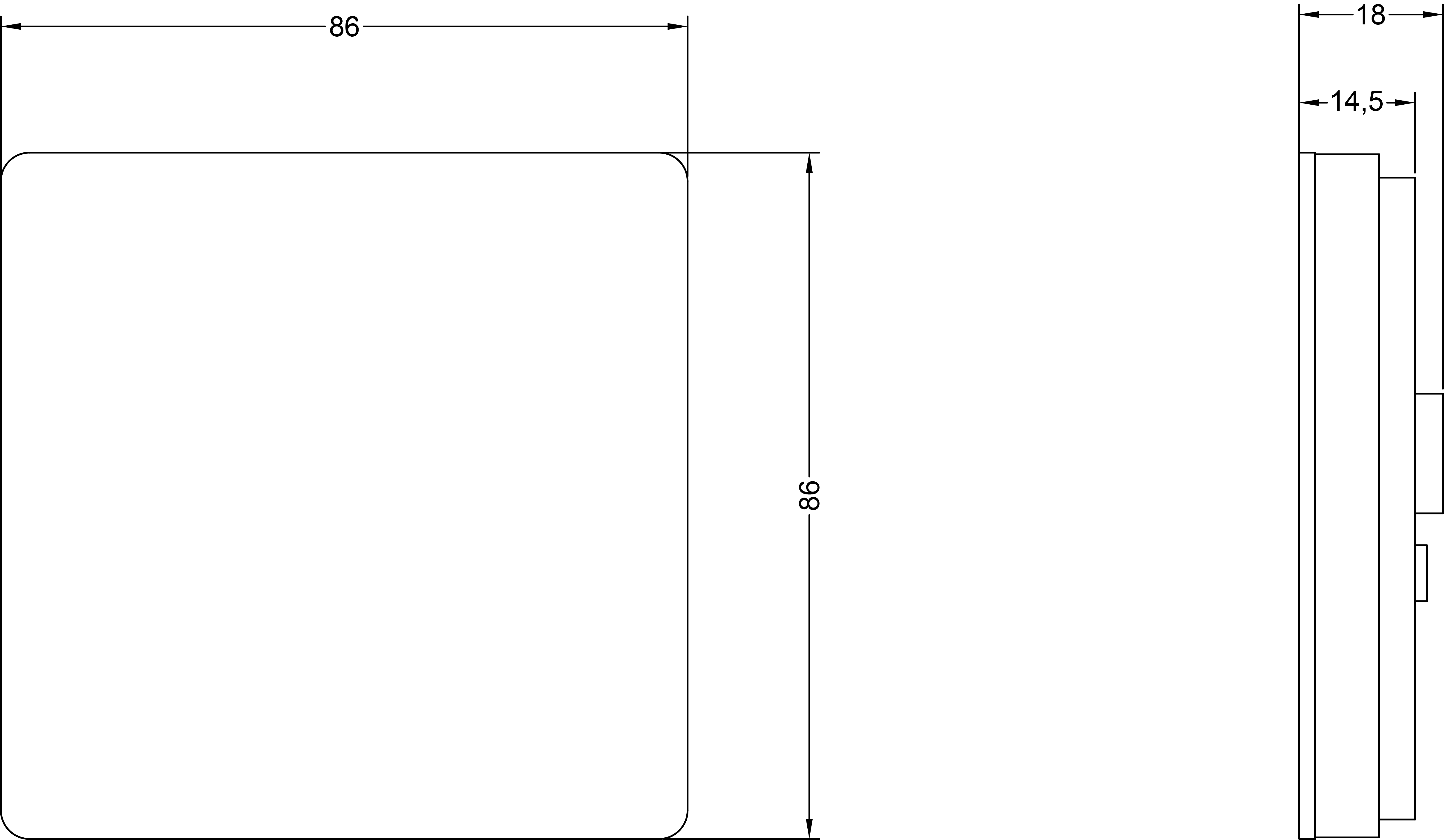
Dimensions [mm]
Touch Panel
Warning!
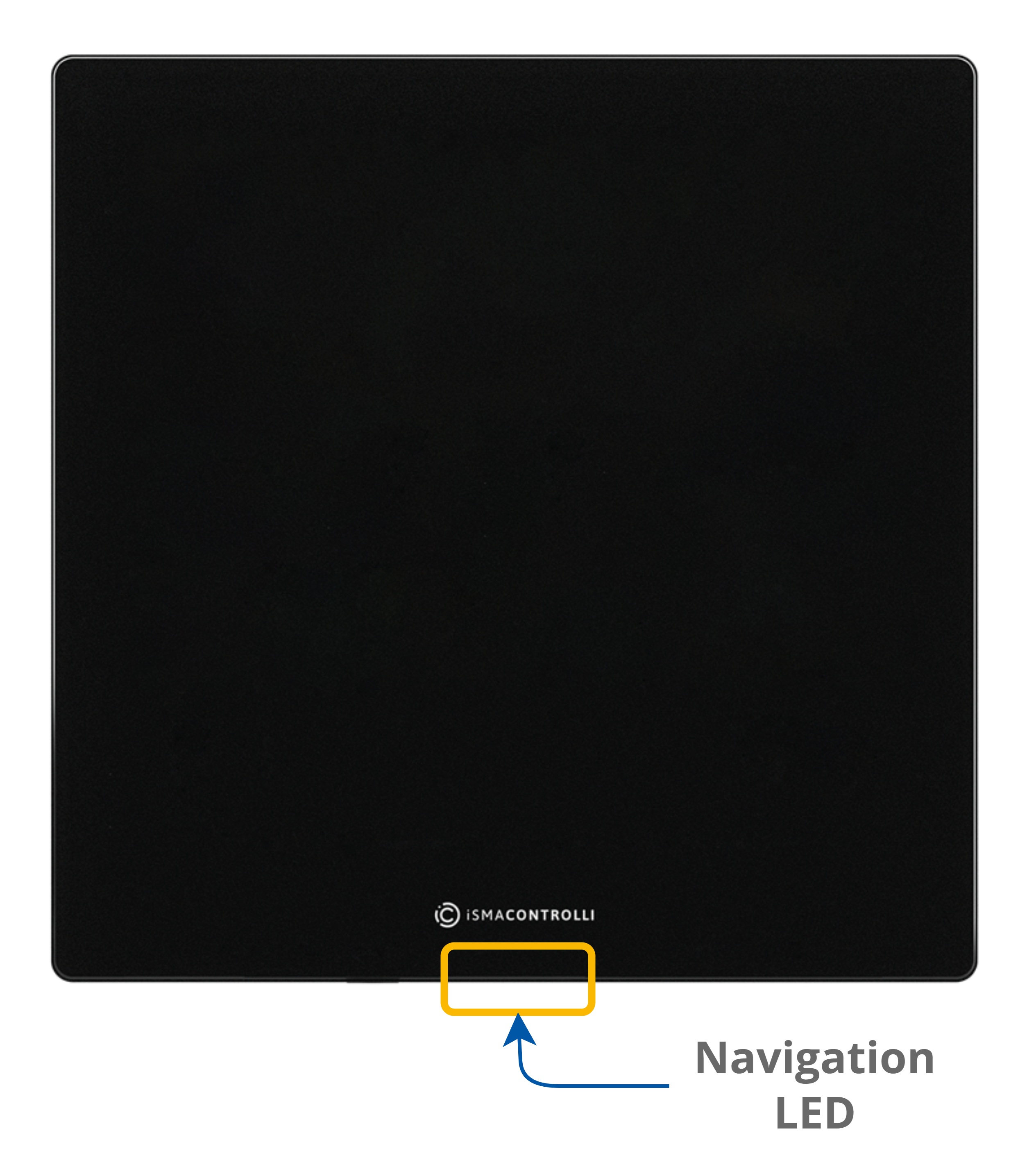
This section does not apply to the Touch Point Network Sensor series, which is not equipped with a touch panel and LEDs.
The only exception is the navigation LED, which works in all Touch Point series.
|
|
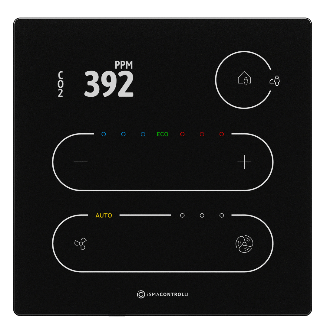
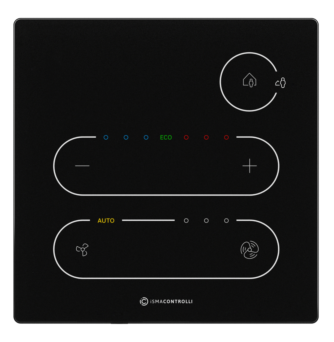
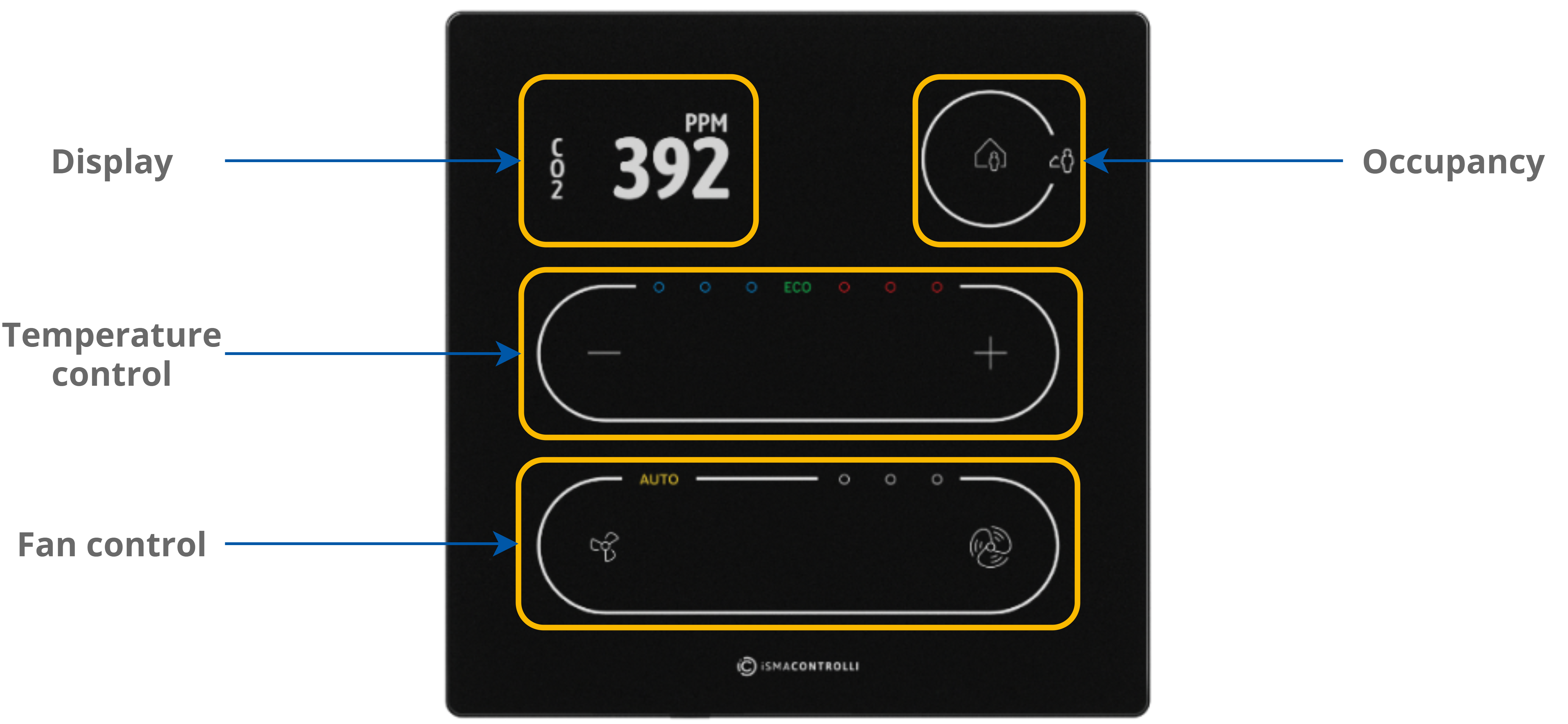
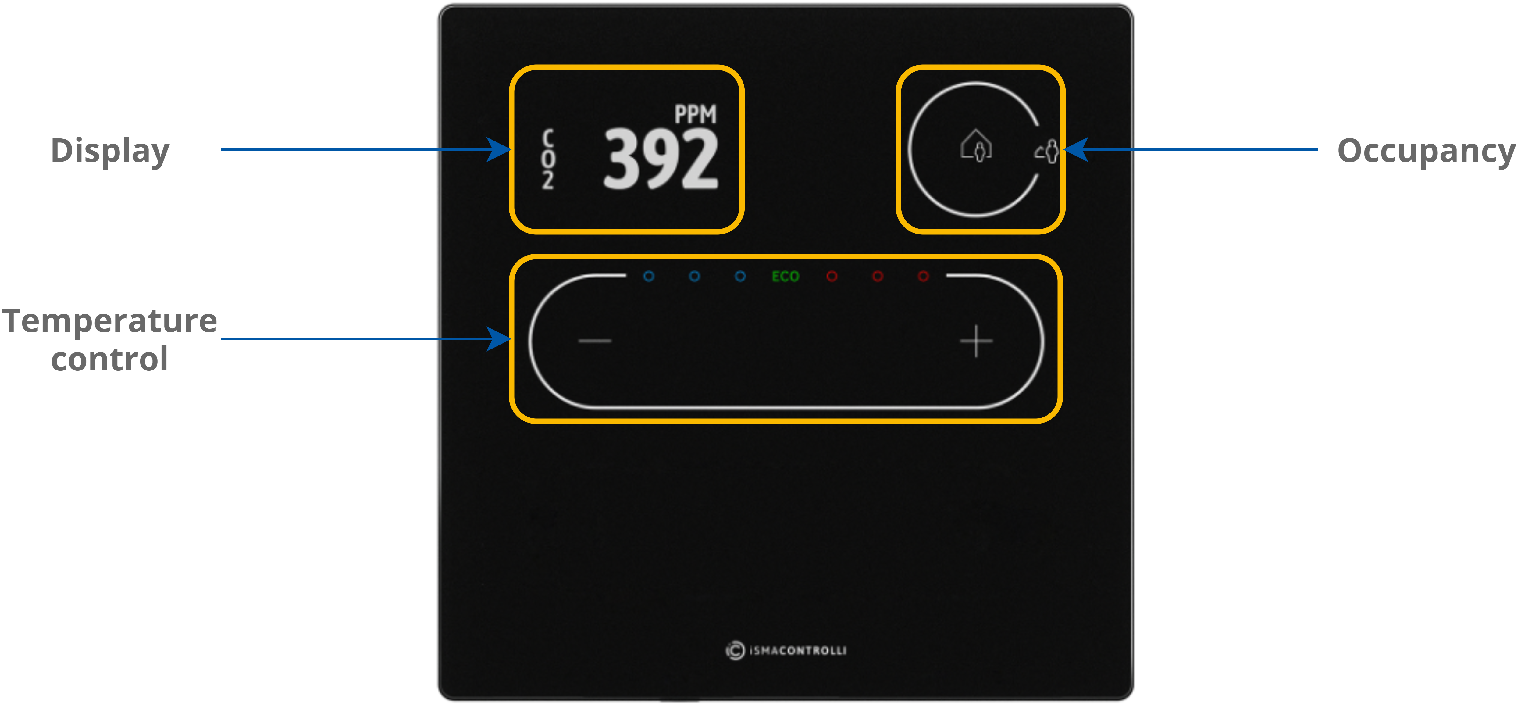
-
5 buttons for occupancy, temperature (–/+), and fan (small fan/big fan icons - only the Touch Point series) control;
-
3 blue and 3 red LEDs for temperature signalization;
-
3 white LEDs for fan signalization (only the Touch Point series);
-
1 white LED for fan auto mode signalization (only the Touch Point series).
Auto-calibration
Touch buttons are cyclically auto-calibrated. During the process, buttons are not responsive; in such case, wait a few seconds and press the button again.
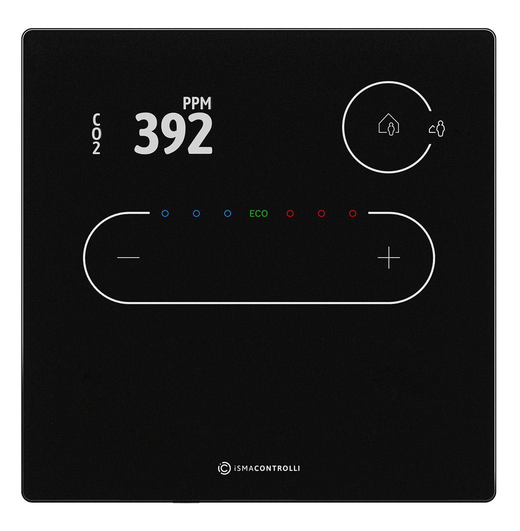
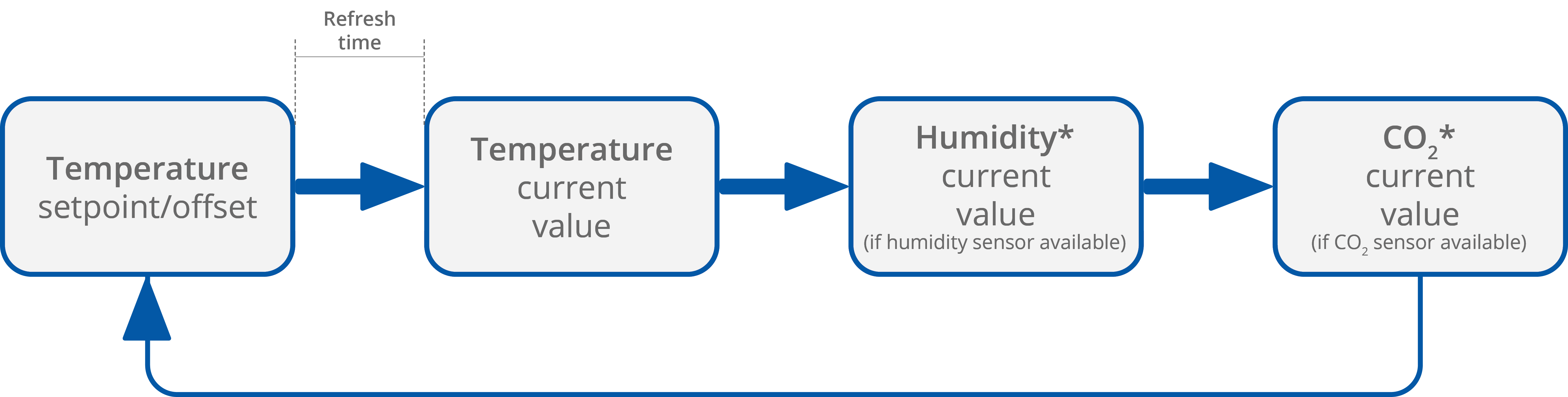
The LCD display shows following information:
-
temperature setpoint or offset (after pushing a + or – button, according to configuration);
-
temperature current value with unit;
-
humidity current value with unit (optionally);
-
CO2 current value with unit (optionally).
Note: Currently displayed parameters change with a frequency set in the 40217 register.
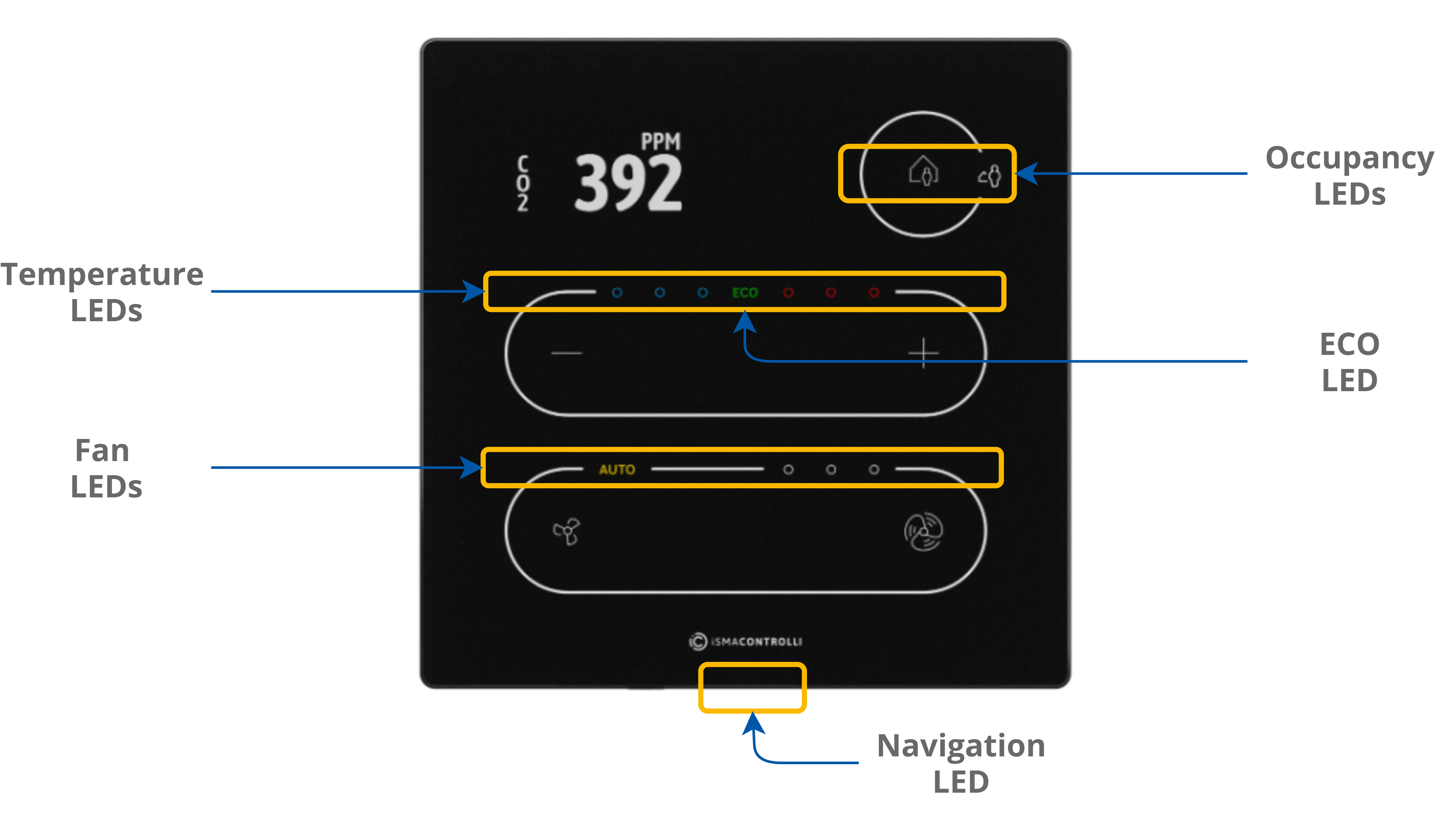
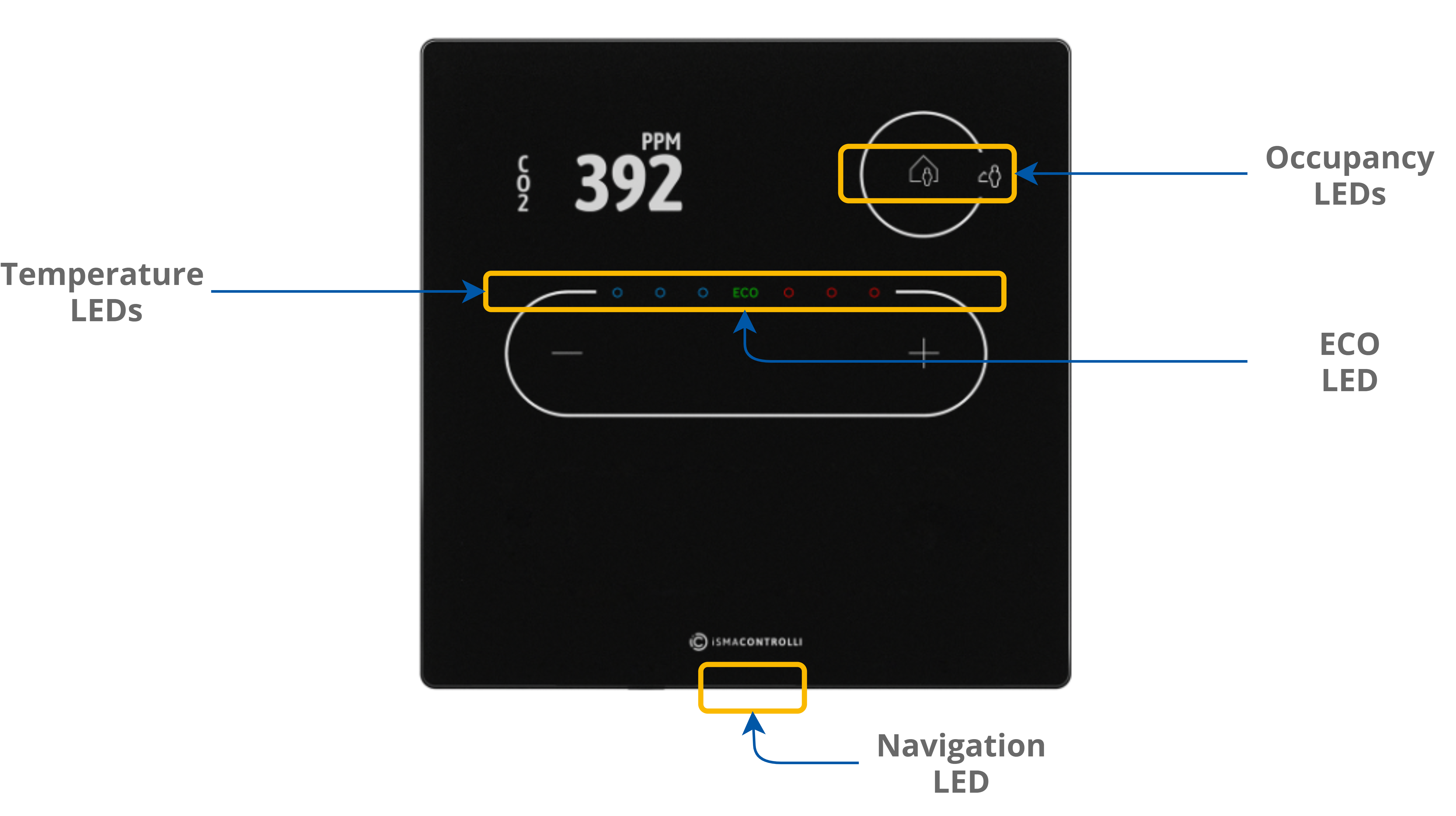
LEDs
|
|
|
The panel is equipped with:
-
2 white LEDs for signalizing occupancy status;
-
3 blue and 3 red LEDs for temperature signalization (cooling or heating);
-
4 white LEDs for fan modes indication (only the Touch Point series);
-
1 ECO LED;
-
1 navigation LED to localize the panel in the dark.
LED Modes
The Touch Point panel works in 3 modes of LED lighting intensity:
-
active: the LED lighting mode after any button on the screen has been touched;
-
idle: the LED lighting mode after a time set from a last button has been touched;
-
standby: the LED lighting mode after a time set from going into the idle mode.
All lighting intensity values in these three different modes can be set in the 40207-40216 Modbus registers.
Buzzer
The Touch Point panel is equipped with a buzzer, which informs about a detected touch with a short sound.
The buzzer also provides a CO2 alarm function, which emits sounds once the CO2 level exceeds a set alarm value. The alarm can be confirmed and muted by pressing any button.
Please note that in the Touch Point Network Sensor series, the CO2 alarm is not active by default.
The buzzer may be activated or deactivated using the DEVICE_CONFIGURATION register/object (bit 0, BUZZER).
|
Register Value |
Description |
|---|---|
|
0 |
Buzzer deactivated |
|
1 |
Buzzer activated |
The BUZZER values
By default, the buzzer is active.