Applicable to OS V1.10
The LightCommand component allows for light control by sending specific commands in one of three ways: to a single device, a group of devices, or broadcast to all devices.
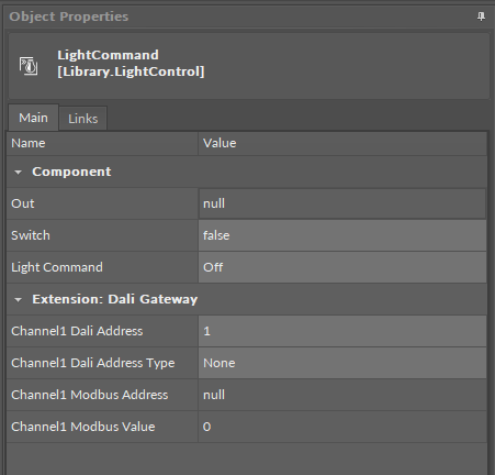
The LightCommand component has the following slots:
-
Switch: receives a signal from a connected monostable switch; on a rising edge invokes a command set in the Light Command slot;
-
Light Command: defines which command will be set in the Out slot:
-
Available values:
-
Off: switches the light off,
-
Up: increases the lighting level,
-
Down: decreases the lighting level,
-
Step Up: increases the target lighting level by 1 increment without fading,
-
Step Down: decreases the target lighting level by 1 step without fading,
-
Recall Max Level: changes the current light output to the maximum level,
-
Recall Min Level: changes the current light output to the minimum level,
-
Step Down and Off:
-
if the target level is zero, lamp(s) are turned off,
-
if the target level is between the min. and max. levels, decreases the target level by one,
-
-
On and Step Up:
-
if the target level is zero, lamp(s) are set to minimum level,
-
if target level is between min. and max. levels, increases the target level by one.
-
-
-
Extensions
DALI
The DALI extension is dedicated to light control in controllers that natively support the DALI protocol. The DALI network has to be configured on the controller for the extension to work properly.
The DALI extension allows the component to connect to a DALI device and control it directly through the DALI network. The extension allows to send commands to a single DALI device, a group of devices, or broadcast to all devices on the network, through an encoded output.
The extension is added from the context menu of the component (Add Extension>DALI).
To process the light control, the DALI extension has to be linked directly to the EncodedSendCommand component in the DALI network:
-
the Channel1 Encoded Output slot to the Encoded Input slot.
The DALI extension has the following slots:
-
Channel1 Dali Address: sets the short address of the DALI device or a group DALI devices to be controlled by the component,
-
Channel1 Dali Address Type: allows to select the target device(s) to send out the command;
-
Available settings: Single, Group, All;
-
-
Channel1 Encoded Output: a 4-byte output value containing information about a command (specified to the component or defined in the relevant slot), and its value specified to be sent out to the addressed device(s):
|
Byte |
Byte 3 (MSB) |
Byte 2 |
Byte 1 |
Byte 0 |
|---|---|---|---|---|
|
Type of encoded information |
Address type |
Address |
Command |
Value |
|
Value |
1 |
5 |
0 |
254 |
|
Final encoded input |
17105150 |
|||
DALI Gateway
The DALI Gateway extension is dedicated to light control in controllers that do not natively support the DALI protocol.
The DALI Gateway extension enhances the component’s functionality by providing a possibility to work through the DALI protocol. The extension allows to determine the DALI device or group of DALI devices to control. With the use of the extension it is also possible to broadcast DALI commands to all connected devices.
The extension is added from the context menu of the component (Add Extension>DALI Gateway).
To process the DALI command, the component has to be linked to the network point component:
-
the Channel1 Modbus Address slot should be linked to the Modbus network point’s Address slot,
-
the Channel1 Modbus Value slot should be linked by Reference through the Data Point to the Modbus network point.
The two above values determine the DALI command to send and the address of the DALI device to send the command to.
-
Channel1 Dali Address: sets the short address of the DALI device or a group DALI devices to be controlled by the component,
-
Channel1 Dali Address Type: allows to set a proper Modbus address slot for a linked network point depending on a number of DALI devices to be controlled (single/group/all),
-
Available values:
-
None: Modbus address is null,
-
Single: Modbus address is 511,
-
Group: Modbus address is 521,
-
All: Modbus address is 531;
-
-
-
Channel1 Modbus Address: the output slot with the Modbus address indicating the destination DALI network point to send the DALI command to;
-
Channel1 Modbus Value: the 16-bit output value comprised as follows:
-
upper 8 bits: 15-8:
-
short address of a single lamp 0-63 for lamp 1 to 64, or
-
short address of a group of lamps 0-15 for a lamp group 1 to 16;
-
-
lower 8 bits: 7-0 represents of a DALI command 0-8.
-
The Channel1 Modbus Value value is set according to the formula:
Channel1 Modbus Value = (Channel1 Dali Address - 1) * 256 + Component Out Value,
where:
Channel1 Dali Address = short DALI device address or DALI group address;
Component Out Value = value of the output slot in the component which the extension has been added to.