Applicable to OS V1.9
The MultistateDataPoint component is a component that represents an analog integer positive value in the application; it reads values calculated in applications and controls local or remote analog outputs. The MultistateDataPoint allows to create standard links to all inputs and outputs.
In order to operate properly the component must be placed in the Application component in the Applications container.
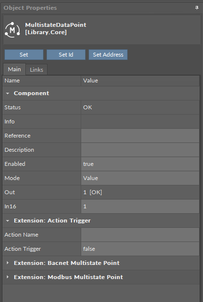
The MultistateDataPoint can operate in two configurations. First, it is a basic configuration with one writable input slot (In16), one output slot (Out), and other basic slots: Mode, Units, Status, Enabled, Description. In the basic configuration, the MultistateDataPoint has native BACnetMultistatePoint and ModbusMultistatePoint extensions.
The MultistateDataPoint has the following basic slots:
-
Status: indicates the current status of the component. If the component works properly, its status is OK; however, it changes accordingly when values in other slots are adjusted.
-
Available information: Disabled, Unlicensed, Error, Overriden, OK;
-
-
Info: slot for future use.
-
Reference: slot for future use.
-
Description: an additional detailed information about a component that may be freely described by the user; the description may contain individual coding defined in the user's system documentation or any other information the user finds applicable.
-
Enabled: change of the slot's value enables or disables the component–if the component becomes disabled, it stops reading values from or transferring values to the linked network points. By default, the component is enabled.
-
Available settings: true (enabled), false (disabled).
-
-
Mode: allows to set a mode of the component, which defines the type of data exposed on specific protocol’s server if it is read-only or writable;
-
Available settings: Value, Input, Output;
-
-
Out: shows a value transferred from the In16 slot in the basic configuration, or from the first non-null input with highest priority in the extended mode; in case there are values on different priorities, only the value from the highest priority slot is transferred to the Out slot, the rest is dismissed.
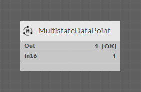
Note: In the Wire Sheet the Out slot is visible as combined slots Out, Units, Priority (which is a source of the Out slot value; shown in the extended mode), and Status.
Note: If labels are set for values in the MultistateDataPoint, the Out slot will display the label. If the Out slot has an outgoing link to another component, the only the numeric value will be transferred.
-
In16: the basic input slot; receives analog values; the In16 value may be set by a Set action;
The MultistateDataPoint has the following basic actions:
-
Set: allows entering an analog value to set the In16 slot;
-
SetId: sets a BACnet object Id of the MultistateDataPoint (exposed in the BACnetMultistatePoint extension);
-
SetAddress: sets a Modbus address of the MultistateDataPoint (exposed in the ModbusMultistatePoint extension).
The extended configuration of the MultistateDataPoint is switched on by adding the AnalogPriorites extension to the MultistateDataPoint component. The extension adds 16 writable input slots to the Data Point. It is added by right-clicking on the MultistateDataPoint component (either in the Wire Sheet or Property Sheet view).
Labels
In MultistateDataPoints it is possible to set labels for different values. Labels are individual representations for default values in the Data Point, for example, it is possible to set individual value for any integer value that will be displayed instead. Labels applied in a component are visible on every component's view (Wire Sheet, Property Sheet, Object Properties, etc.).
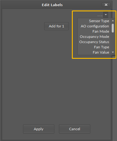
To edit labels for the MultistateDataPoint, go to the component's context menu and select the Edit Labels option. The dialog window appears to edit labels for each value:
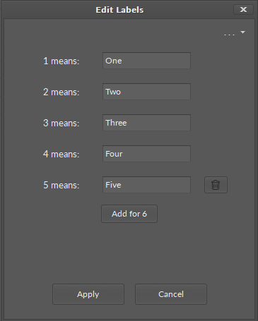
In the top right corner of the dialog window, the dots/arrow button displays preset lists of labels for specific purposes:
Note: Please note that labels are only representations of the integer values of the MultistateDataPoint, they are not string values. When transferred by a link to another component, the source integer value is sent without an assigned label.
Tags
Tags are labels or key-value pairs that provide metadata to identify, categorize, and organize data from devices and systems like HVAC, lighting, or security. They enable interoperability by providing a standardized way to understand data from different sources, which improves data quality, facilitates automation, simplifies integration, and allows for more efficient data analysis.
Application Structure for Tags
Applying tags in the nano EDGE ENGINE is based on a semantic approach that ensures consistent data structure which is easily usable by the nanoWebUI™ and by third-party systems. Tags are applied at the Equipment and Data Point levels, where Equipment serves as the logical container defining what is being controlled, and Data Points represent the measured or commanded values associated with that equipment. This structured model ensures that tagged data is immediately usable by platforms capable of communicating through standardized tag-based HTTP APIs, e.g., Haystack.
Note: Tags can be only applied to the Equipment components and Data Points. Other component types are not supported.
It is therefore recommended (however, not mandatory) to use the following structure when creating applications:
-
Applications container
-
Application component
-
Equipment component
-
Data Point(s)
-
other components
-
-
Equipment component
-
Data Point(s)
-
other components
-
-
-
A required condition for using tags is that the Tagging library is installed on the device and the Tagging service is available in the Services container. Both are a default part of the nano EDGE ENGINE V1.9 and are not compatible with previous versions.
Tags are available in two formats: auto-tagging and manually added.
Auto-tagging
The auto-tagging purpose is to automatically assign appropriate tags and markers based on various conditions. This system ensures consistency and reduces manual work when creating or modifying applications.
If enabled, the auto-tagging mechanism is executed in the following situations:
-
after all components are loaded during a device’s start-up,
-
when a component is renamed,
-
when a component is redefined (e.g., extensions/tags are added/removed),
-
when a new component is added,
-
when a component is moved within the Workspace tree,
-
when multistate labels are modified.
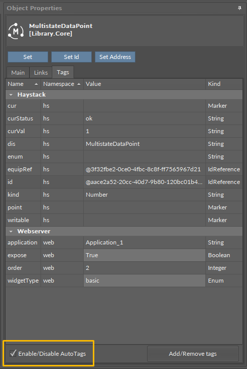
Enabling/disabling the auto-tagging mechanism for the Data Point is possible in the Tags tab in the Data Point’s Object Properties window:
Auto-tags available for the MultistateDataPoint are the following:
|
Tag |
Description |
|---|---|
|
|
Marker indicating a current value support (read-only) |
|
|
Status of the Data Point's current value (read-only) |
|
|
Current output value (read-only) |
|
|
Display name of the component (read-only) |
|
|
Derived from multistate labels (read-only) |
|
|
Reference to the parent Equipment component (only if located under it) (read-only) |
|
|
Unique identifier of the Data Point (read-only) |
|
|
Value kind (read-only) |
|
|
Marker (read-only) |
|
|
Added if the Data Point’s mode is set Output or Value; removed when changed to Input (read-only) |
|
|
Reference to the application (for the nanoWebUI order) |
|
|
User-editable flag to show on the nanoWebUI |
|
|
Order for widgets on the nanoWebUI |
|
|
Widget type for the nanoWebUI |
Manual Adding Tags
Outside of the auto-tagging mechanism, it is also possible to manually add tags.
The list of available tags is comprised of two tags dictionaries available: Haystack and Webserver.
Haystack Tags Exceptions
The list of tags in the Haystack tag dictionary corresponds with the Haystack standard: Tags in Project Haystack; however, there are some differences. The dictionary does not include the following tags:
list, dict, grid, scalar, xstr, choice, symbol, is, na, remove, of, quantities, quantityOf, tagOn, tags, containedBy, contains, def, defx, inputs, outputs, reciprocalOf, relationship, span, mlIdentificationPeriod as well as tags of types: feature, filetype, lib, op, list, dict, grid.
These tags are not relevant for the data modelling based on Data Points and the Equipment component (in the application structure).
Adding and editing tags are possible in the Tags tab of the Data Point’s Object Properties window.
Tip
To access the Tags tab:
-
go directly to the Object Properties of the component,
-
go to the Tag Manager and click on the component,
-
or use the Edit Tags option of the component’s context menu:
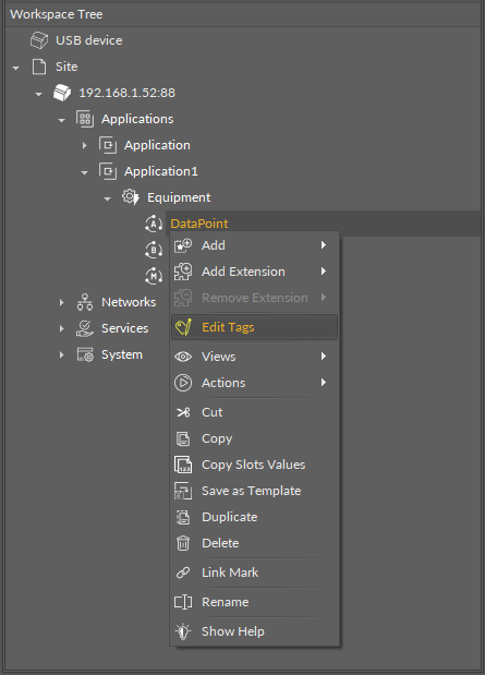
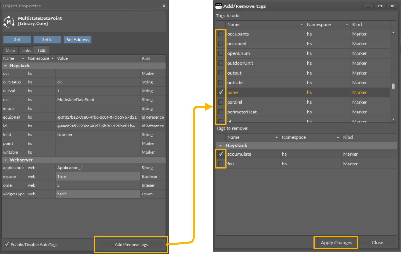
In the Tags tab, use the Add/Remove Tags button to open a dialog window, where it is possible to select new tags to add or to remove using check boxes. Confirm changes with the Apply Changes button. Tags currently added to the component are listed in the Tags tab.
Extensions
Data Points can have their functionality modified by extensions. The MultistateDataPoint is originally equipped with the BACnetMultistatePoint and ModbusMultistatePoint extensions (these cannot be added or removed), but other extensions, which offer different functionalities, can be added or removed as necessary. Extensions are added by right-clicking the MultistateDataPoint, either in the Wire Sheet or Property Sheet view, Application Manager, or in the Workspace Tree.
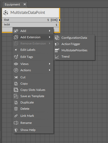
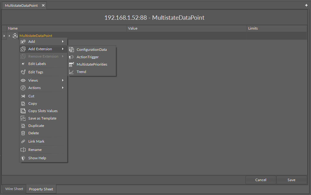
From the context menu, select the Add Extension option; add the extension from the list of available options.
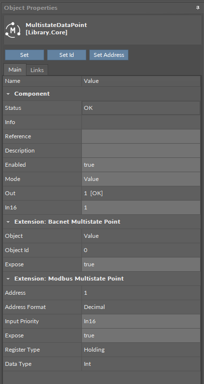
BACnetMultistatePoint
The BACnetMultistatePoint extension expands the MultistateDataPoint's functionality giving it an option to expose it to the BACnet IP network as an Analog Value object, and, otherwise, it allows to manually hide it from the network yet preserving its function in the application. It also transfers information to the BACnet IP network about the MultistateDataPoint's status. The extension is native (cannot be removed), and is visible along with the regular slots and actions of the MultistateDataPoint as a separate, integral part in the Object Properties view.
The extension has the following slots:
-
Object: a read-only slot showing a type of BACnet object attributed to the extension;
-
ObjectID: a BACnet object ID, which is automatically numbered from 0 up;
Worth to notice
From nano EDGE ENGINE V1.7, it is possible for the client to remotely change the exposed Data Point’s object ID over BACnet.
-
Expose: enables the Data Point to be recognized within the BACnet IP network;
-
Available settings: true (exposed), false (hidden).
-
ModbusMultistatePoint
The ModbusMultistatePoint extension expands the MultistateDataPoint's functionality giving it an option to expose it to the Modbus TCP/IP network as a Modbus point, and, otherwise, it allows to manually hide it from the network yet preserving its function in the application. It also transfers information to the Modbus TCP/IP network about the MultistateDataPoint's status. The extension is native (cannot be removed), and is visible along with the regular slots and actions of the MultistateDataPoint as a separate, integral part in the Object Properties view.
The extension has the following slots:
-
Address: a read-only slot showing a Modbus register, which the Data Point is exposed on;
-
Address Format: a read-only slot showing a register address format;
-
Available information: decimal, Modbus, HEX;
-
-
Input Priority: allows to select the input number in the Data Point, which the value from the register is synchronized on;
-
Expose: enables the Data Point to be recognized within the Modbus TCP/IP network;
-
Available settings: true (exposed), false (hidden);
-
-
Register: a read-only slot showing the type of the register used;
-
Available information: holding register;
-
-
Data Type: allows to select a value data type;
-
Available settings: integer (default), signed integer, long, signed long, float, double.
-
Apart from the BACnetMultistatePoint and ModbusMultistatePoint, it is possible to add the following extensions to the MultistateDataPoint:
Trend
The Trend extension allows to save values from Data Points in a database. For a trend to be saved in the Trends service, it is required to add the Trend extension to the Data Point.
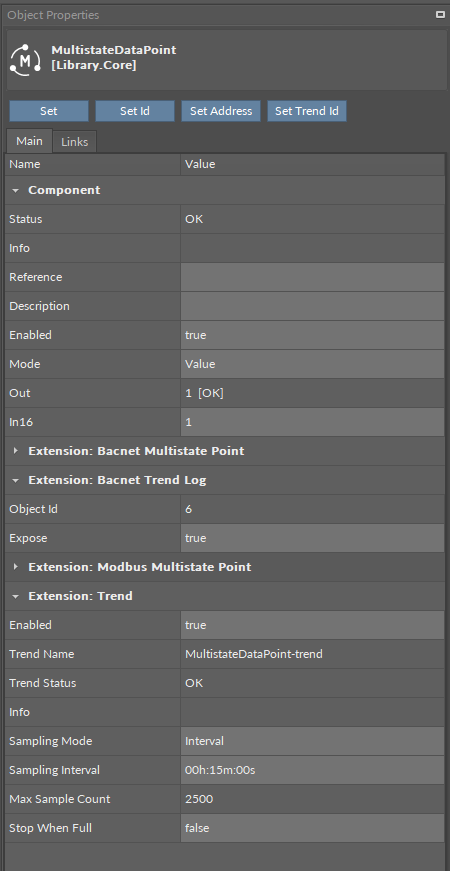
The Trend extension has the following slots:
-
Enabled: allows to enable or disable the trend;
-
Trend Name: shows the name of the trend;
-
Trend Status: informs of the extension’s status;
-
Available information:
-
Disabled (the Data Point, Trend extension, or Trends service is disabled),
-
Unlicensed (the Data Point is unlicensed),
-
Stopped (the number of saved samples is equal to or greater than Max Sample Count and the Stop When Full slot is set to true),
-
OK;
-
-
-
Info: provides a detailed information about the Disabled status of the component;
-
Available information:
-
Trend extension disabled: the Enabled slot in the Trend extension is set to false,
-
Parent (Data Point) disabled: the Enabled slot in the Data Point is set to false,
-
Parent (Data Point) unlicensed: the Data Point, which the Trend extension is added to, is unlicensed,
-
Trends Service disabled: the Enabled slot in the Trends service is set to false;
-
-
From OS V1.8, the Info is a numerical slot, which displays a correlated text information:
|
Numerical value |
Displayed information |
|---|---|
|
0 |
No information displayed in the Info slot |
|
1 |
Trend extension disabled |
|
2 |
Parent (Data Point) disabled |
|
3 |
Parent (Data Point) unlicensed |
|
4 |
Trends Service disabled |
-
Sampling Mode: allows to set a sampling mode for saving data;
-
Available settings:
-
COV (triggers saving the sample when the Data Point’s Out slot value changes and this change is bigger than the Deadband slot’s value),
-
Interval (triggers saving the sample when time reaches the value of Sampling Interval slot’s value),
-
COV Interval (triggers saving the sample in both the above cases);
-
-
-
Sampling Interval: (available only if interval or COV interval mode is selected) time value, which triggers saving trend data;
-
Max Sample Count: shows a number of maximum (2500) samples that can be saved in the database for the trend;
-
Stop When Full: allows to stop saving trend data if the Max Sample Count number is reached;
-
Available settings: false (trend overwrites the oldest samples), true (trend stops executing).
-
BACnet Trend Log
When the Trend extension is added to the Data Point, it automatically adds another extension in the Data Points view: the BACnet Trend Log extension. This extension allows to manage the trend’s BACnet exposition to the network and adds a BACnet ID if exposed.
The BACnet Trend Log extension has the following slots:
-
Object Id: shows an automatically assigned BACnet object ID number if the trend is exposed to the BACnet network;
-
Expose: allows to enable or disable the trend’s exposition to the BACnet network; by default, the trends is exposed to the network.
The BACnet Trend Log extension has the following action:
-
Set Trend Id: allows to set the object ID value for the trend exposed to the BACnet network.
Configuration Data
The Configuration Data extension has no slots. Its functionality is fully achieved by adding it to the Data Point. It is automatically enabled and allows the Configuration Data service to save and upload slots values of the Data Point.
MultistatePriorities
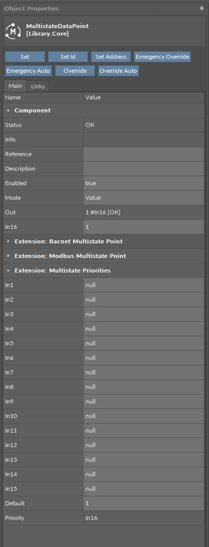
The MultistatePriorities extension adds fifteen writable input slots and the default (lowest) priority slot to the MultistateDataPoint. The extension includes the Priority slot indicating, which slot is transferring value to the Out slot. The AnalogPriorites extension adds In1–In15 slots and the Default slot, which is the lowest, 17th priority. The extension also introduces new actions to the Data Point: EmergencyOverride, EmergencyAuto, Override, and OverrideAuto.
The MultistateDataPoint has the following slots available in the MultistatePriorities extension:
-
In1-In15: input slots providing values to the Out slot (from 1 to 16, the highest priority is In1); only the highest priority value is provided to the Out slot, the rest is dismissed. All input slots are linkable. In the extended mode, the In1 and In8 slots have actions available for overriding their values.
Note: By default, only the In16 is displayed in the Wire Sheet. In case any other input slot receives a value via link, is it displayed in the Wire Sheet along with the In16. Only the null input, which is a lack of value, allows the higher priority input to be dismissed–zero (0) is still a value that will be provided to the Out slot.
-
Default: the 17th, lowest priority input slot; allows to introduce a default value to the Data Point in case there are no links providing values from other components.
Note: According to BACnet requirements, the Default slot value can never be null; if no other value is set on the slot, it is zero (0).
-
Priority: shows, which slot is currently providing the value to the Out slot.
The MultistateDataPoint has the following actions available in the MultistatePriorities extension:
-
EmergencyOverride: enables entering an analog value to the In1 slot;
-
EmergencyAuto: sets the null value to the In1 slot (cancels the EmergencyOverride action);
-
Override: enables entering an analog value to the In8 slot;
-
OverrideAuto: sets the null value to the In8 slot (cancels the Override action).
Note: If the link is connected to the slot that may be affected by an action, the value coming from the link connection has priority over the manually evoked action.
ActionTrigger
The ActionTrigger extension is designed to invoke any action that is available for the component. The extension triggers an action selected in the Action Name on the rising edge of the Action Trigger slot. If the action has parameters to set, the parameter is taken from a relevant slot automatically added to the extension (Analog Value/Binary Value/String Value).
It is possible to add more than one ActionTrigger extension to the component (for example, one for each action in the component).
The extension is added from the context menu of the component.
The ActionTrigger extension has the following slots:
-
Action Name: allows to select an action to invoke;
-
Action Trigger: triggers an action selected in the Action Name slot;
-
Action Analog Value/Action Binary Value/Action String Value: a slot added automatically to the extension if an action selected in the Action Name slot has any specific parameters to set (depending on the type of action and its parameters, the relevant type of value is matched).